L’innovation française depuis 1965
P. 5
L’innovation française depuis 1965
INPUT / OUTPUT / POWER SUPPLY
Type of connection
Cross section
MCP2,8 - 21Pts (BROWN) housing connectors
Ref. Scheiber 0E.CON1430
Ref. Tyco 8-968975-1 MCP2,8GEH21P
MCP2,8 Receptacle 0,5-1,0mm2 tinned
Ref. Scheiber 0E.CLP360
Ref. Tyco 1-968849-1
Extraction tool for MCP contacts
Réf. Tyco 1-1579007-2
CAN BUS 2 x CAN connectors type 6-way Micro-Fit
PROTECTION TO BE PROVIDED ON THE SUPPLY LINE
Protection rating
Protection location
Fuse or circuit breaker 5A
Accessible and identied for the user
Connection
Mounting
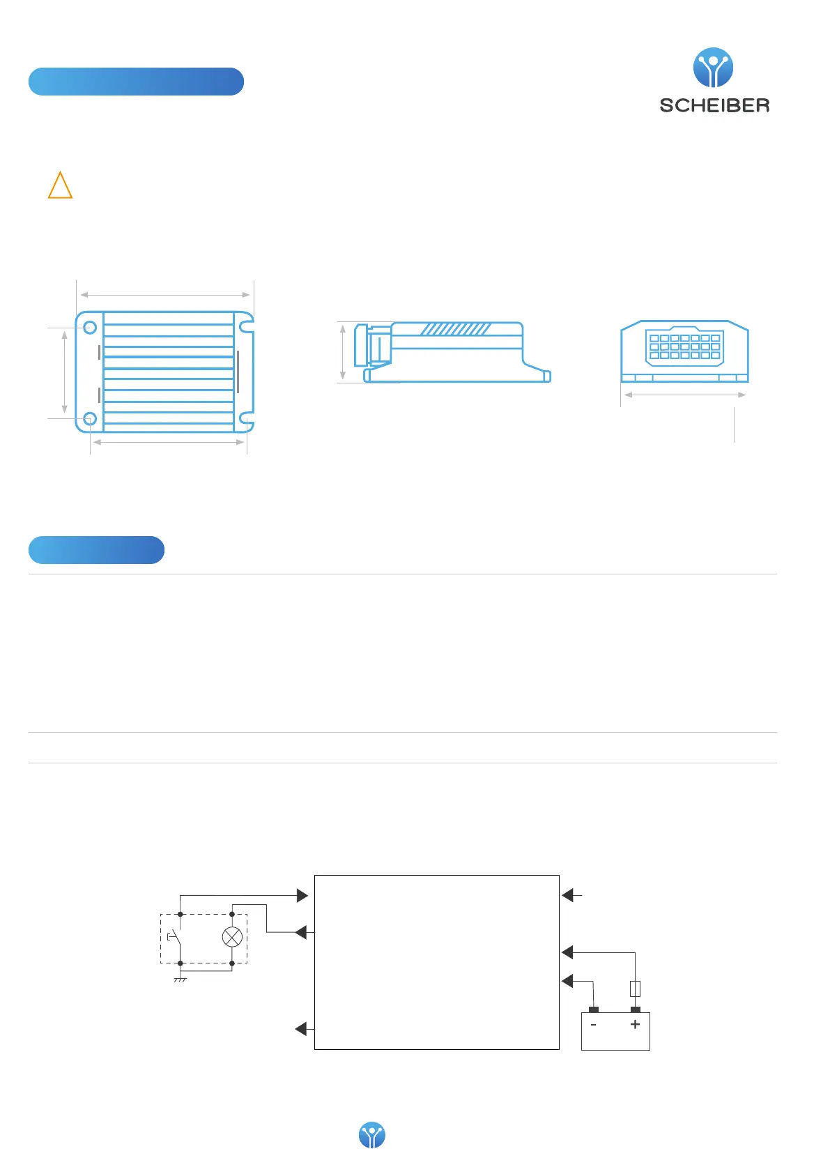
Mounting distance :
100 x 59 mm
36,31
77,51
119,50
59
100
Inpout 1 ... 6 (-)
Output 1 ... 6 (+)
Output 7 (+)
*
* To power a backlight indicator for example
17
Coding
19
21
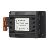
BLOC 10
Illuminated push-button
Installation instructions
• This device must be placed in a place protecting it from any risk of water splashing. Install in a ventilated location
• Do not install on supports that are sensitive to heat, such as carpet or PVC ooring, etc.
• The product must be installed away from heat and humidity
!
WARNING: Connection/disconnection with power on
Do not perform connection or disconnection with power on.