L’innovation française depuis 1965
P. 6
L’innovation française depuis 1965
Crimp pin Designation Description
1 S1_NO NO Contact Relay n°1
2 S1_C Common relay contact n°1
3 E1_NUM_PLUS Plus digital input for momentary switches N°1
4 S2 _NO NO Contact Relay n°2
5 S2 _C Common relay contact n°2
6 E2_NUM_PLUS Plus digital input for momentary switches N°2
7 S3_NO NO Contact Relay n°3
8 S3_C Common relay contact n°3
9 E3_NUM_PLUS Plus digital input for momentary switches N°3
10 S4_NO NO Contact Relay n°4
11 S4_C Common relay contact n°4
12 E4_NUM_PLUS Plus digital input for momentary switches N°4
13 S5_NO NO Contact Relay n°5
14 S5_C Common relay contact n°5
15 E5_NUM_PLUS Plus digital input for momentary switches N°5
16 S6_NO NO Contact Relay n°6
17 S6_C Common relay contact n°6
18 E6_NUM_PLUS Plus digital input for momentary switches N°6
19 + BAT Power supply input 8-32VDC
20 CODING Coding input
21 MASS Battery mass
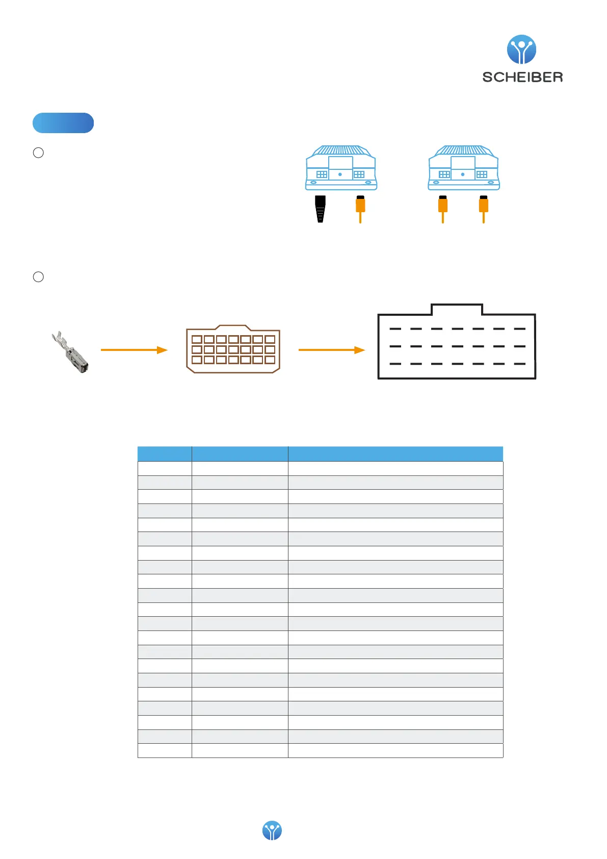
Wiring
1
2
Connect to each connector:
- either a CAN connection cable
(to another Multibloc compatible device)
- or a 120Ω impedance matching plug.
Connect the equipment to the pins according to the numbering available in the table below, then plug
the MPC connector into the TYCO receptacle.
or
120Ω
Termination
CAN
cable
CAN
cable
CAN
cable
1
2
3
4
5
6
7
8
9
10
11
12
13
14
15
16
17
18
19
20
21
TYCO receptacleMCP connectorcrimp pins x21