ated by persons familiar with it and instructed in its op-
eration and procedures. Arbitrary alterations to the ma-
chine release the manufacturer from all responsibility
for any resulting damages.
• The machine may only be used with original accessories
and original tools made by the manufacturer.
• Any other use exceeds authorization. The manufacturer
is not responsible for any damages resulting from unau-
thorized use; risk is the sole responsibility of the opera-
tor.
Scope of delivery
Band saw
Sawing table
Longitudinal stop
Dust bag connector
Operating instructions
Push stick
Accessory bag
Hexagonal spanner SW 0/13
Hexagon socket head wrench SW 4/SW 5
Special accessories - page GB13
Specifications
Passage width 306 mm
Passage height 160 mm
Table size 400 x 548 mm
Cutting speed 370 – 750 m/min
Saw band length 2360 mm
Height up to tabletop 515 mm
Height up to tabletop with
underframe 1050 mm
Overall height without underframe 1150 mm
Overall height with underframe 1680 mm
Overall width 825 mm
Overall depth 540 mm
Slewing range of the table -17°/+45°
Overall weight without underframe 69 kg
Overall weight with underframe 77 kg
Motor Alternating current
Rotary current
Nominal consumption P1 (kW) 0,80
0,72
Delivery of power P2 (kW) 0,55
0,55
Noise parameters
The noise emission values determined according to EN
23746 for the sound level and according to EN 31202
(coefficient of correction k3 calculated according to Ap-
pendix A.2 of EN 31204) for the sound level at the work-
place are as follows, based on the working conditions list-
ed in ISO 7904 Appendix A:
Sound level in dB
Idle running LWA = 80.3 dB(A)
Operation LWA = 100.2 dB(A)
Sound level at the workplace in dB
Idle running LpAeq = 64.1 dB(A)
Operation LpAeq = 82.9 dB(A)
A measurement uncertainty allowance K = 4 dB applies to
the mentioned emission values.
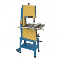
Machine description
Due to its perfected design, the machine offers a versatile
application for processing wood and plastics in the work-
shop.
The upper and lower bandwheel is protected by a fixed
guard and an articulated cover. Upon opening the cover,
the machine is switched off. Switching on again is only
possible with the cover closed. The non-cutting part of the
sawbelt above the table top is covered by a guard fixed to
the sawbelt guide, the latter being protected against inad-
vertant opening by the fixed guard of the upper band
wheel. The non-cutting part of the sawbelt under the table
top is protected by a fixed cover.
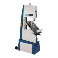
The swivelling range of the table from -20° to +47° allows
versatile cutting possibilities (e.g.)
• Longitudinal cuts
• Cross cuts
• Diagonal cuts
• Curved and irregular cuts
• Cuts for dovetails and tenons
• On-edge cuts of squared beams
Please consult also the working hints in the operating in-
structions.
Completion
Assembly tools
1 engineer’s wrench SW 10/13
For reasons of packaging technology, the tabletop, the
handle, and the handwheel are not mounted.
Installation of the tabletop, Fig. 1
1. Open the case cover, and set the slewing segments to
30°.
2. Loosely screw the tabletop.
4 hexagon head cap screws M 8 x 16
4 serrated lock washers A 8,4
Fig. 2
Turn the tabletop into the 0° position, and tighten the
clamping lever.
Fig. 3
Align the tabletop as follows:
1. Put a straight wood border with a length of approxi-
mately 50 cm on the table and put it against the up-
ward and downward parts of the saw band.
2. Put a shifting square against the wood border and the
groove edge of the table. Align the table, and fasten
the two front hexagon head cap screws on the table.
3. Release the clamping lever of the slewing segments
by means of a quarter turn, and pull the back seg-
ment outwards. Fasten the two back hexagon head
cap screws on the table. Thus, you achieve a smooth
slewability.
Fig. 4
1. Use the adjusting screw on the rear of the machine to
align the table in a right angle to the saw band.
– Use the shifting square –
2. Fix the adjusting screw by a locknut, and fasten the
clamping lever.
GB9