STEP 1
For the adjustment of the
end positions the selector-
switch and the control-
switch have to be horizontal.
STEP 2 **
Push the hand leaver down
and move the hand wheel
while pushing. Close the
valve with the hand wheel.
After reaching the „CLOSE“
position of the valve turn 0,5
to 1 revolution back to con-
sider a possible over-run.
STEP 3
Unscrew the cover of signal
unit to get to the travel
device.
Travel-device
STEP 4
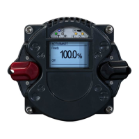
Go up with the black
control switch to the status
menu S4.
STEP 5
Turn the slotted screw
from travel device unit until
„Pos“-value is at 10.0.
1) If you have a mech.
position indicator turn at the
messing wheel.
STEP 6
Go with the black control
switch from menu S4 down
to parameter „1.2 End limit
CLOSE“.
You see on the display
„EDIT?“
STEP 7
Confi rm the question
„EDIT?“ with a short pan of
the red selector switch to
get into the Edit-Mode.
You see on the display
„SAVE?“
STEP 8
Push the red selector
switch down until it locks.
You see on the display
„TEACHIN“(that means
the „Pos“ value which was
setted manually will be
automatically assumed)
STEP 9
Now let the red selector
switch spring back in the
„OFF“ position.
STEP 10
Now pan the red selector
switch up and let it rebound
to save the changed
parameter. You can see on
the display that „SAVE?“
changes to „EDIT?“ The
travel end position „CLOSE“
is now adjusted.The LED for
position „CLOSE“ is glowing.
STEP 11 ***
Push the red selector switch
down, lock it in „LOCAL“
position. Move the black
control switch up to open
the valve. Before the valve
is fully open let the black
control switch rebound in
„STOP“ position. After that
bring the red selector switch
back in „OFF“ position.
STEP 12 **
Both switches are in neutral
horizontal position. Push
the hand lever down while
moving the hand wheel.
Open the valve with the
hand wheel. After valve is in
„OPEN“ position turn 0,5 to
1 revolution back to consider
a possible over-run
STEP 13
Go with the black control
switch down to parameter
„1.1 End limit OPEN“.
You see on the display
„EDIT?“
STEP 14
Confi rm the question
„EDIT?“ with a short pan of
the red selector switch to
get into the Edit-Mode.
You see on the display
„SAVE?“
STEP 15
Push the red selector
switch down until it locks.
You see on the display
„TEACHIN“.
STEP 16
Now let the red selector
switch rebound into the
neutral position „OFF“
STEP 17
Now pan the red selector
switch up and let it rebound
to save the changed
parameter. You can see on
the display that „SAVE?“
changes to „EDIT?“ The
travel end position „OPEN“
is now adjusted.The LED for
position „OPEN“ is glowing.
STEP 18
Push the red selector switch
short down the get back to
the main display. Mount the
cover of the signal unit and
fasten the screws. ATTEN-
TION: Pay attention that the
sealing is mounted correct.
OPEN and CLOSE the
valve to make a test drive.
1)
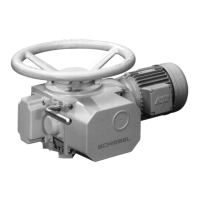
Adjustment of the travel end positions for right closing valves
It is assumed that the actuator has been correctly assembled and electrically connected
CAUTION – use this short instruction always in combination with main instruction manual!
* This short instruction do not replace our main instruction!
* It is designed for skilled people who are acquaint with our main instruction in which safety instructions, mounting,
handling and start-up are described.
* The main instruction must be always available!
STEP 19: If the valve should be closed by torque the Parameter „P 1.4 End limit Switch off CLOSE“ must be changed to value „1 – by torque“ and saved.
** The hand lever de-clutchs automatically during electr. mode, so please DO NOT try to push the hand lever manually up!
*** Stop the drive early enough before reaching the limit position and pay attention to the over-run to avoid damages at the valve or the gearbox!
NOTE:
- During the adjustment of left hand closing valves proceed exactly as if the valve would be right closing. Turn the hand wheel right and adjust end limit CLOSE (though valve is
opened). At the end edit Parameter „P 1.5 End limit Closing direction“ to value „1“ – inverse (ccw). The cross-bonding of all signals and commands happens automatically by the
control unit.
- The LED indication of the valve positions CLOSE & OPEN can be changed in parameter „P 1.7“ (standard: CLOSE=GREEN, OPEN=RED)
page 3
 Loading...