Do you have a question about the SCHIEBEL AB3 and is the answer not in the manual?
Defines the scope and firmware version of the operating instructions.
Warns about hazardous voltages and mandates qualified personnel for electrical work.
Stresses the importance of following maintenance guidelines for safe operation.
Highlights risks of injury or damage from ignoring warnings.
Emphasizes correct handling and commissioning for safe and proper operation.
Mandates adherence to specific standards for electrical installations in hazardous zones.
Specifies that maintenance on open actuators requires de-energized state and prohibits reconnection.
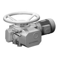
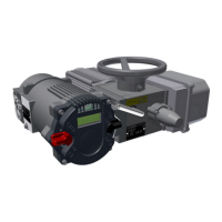
Provides a general overview of the actuator and its key components.
Explains how to locate and interpret serial numbers and nameplates for identification.
Describes the two operational modes: open-loop and closed-loop control.
Details the IP protection systems and necessary precautions for their effectiveness.
Advises on optimal mounting positions, especially for outdoor or splash zone applications.
Defines the standard clockwise and counter-clockwise rotation directions for actuator operation.
Explains the integrated electromechanical and electrical protection devices for actuator safety.
Describes torque protection using plate springs and a potentiometer connected to the control unit.
Details the function and adjustment of mechanical torque switches for rotation control.
Covers electrical protection mechanisms including temperature switches and fuses.
Lists the specified operational temperature ranges for different actuator types.
Outlines the inspection report and pre-set end positions provided upon delivery.
Describes the bilingual information tag attached to the actuator with key operational data.
Warns against using the handwheel for hoisting; recommends soft belts.
Mandates the removal of silica gel from the connection compartment before initial startup.
Provides essential precautions to prevent damage during actuator storage.
Details specific instructions for storing actuators for periods exceeding six months.
Warns that extensive varnishing is prohibited for explosion-proof actuators due to electrostatic charge concerns.
Guides through the process of mechanically connecting the actuator to fittings or gears.
Explains how to rotate the control unit and the importance of avoiding direct sunlight.
Advises protecting the control unit from direct sunlight to prevent potential malfunctions.
Details the procedures and safety requirements for establishing electrical connections.
Emphasizes that electrical connections must be performed by qualified personnel following all relevant regulations.
States the necessity of de-energizing equipment before electrical work and confirming the absence of static discharge.
Advises verifying power supply voltage and frequency against the actuator's connection data.
Mentions connection via terminals for explosion-proof actuators or specific customer requests.
Recommends connecting power for heating effect if commissioning is delayed after electrical connection.
Instructs to remove silica gel from the connection compartment before proceeding with commissioning.
Reminds users to perform mechanical pre-adjustment and other settings during commissioning or after disassembly.
Notes that the torque unit is factory set and should not be altered.
Explains the procedure for switching the actuator to manual operation using the hand lever.
Details the mechanical pre-setup steps required for actuators equipped with a travel potentiometer.
Guides on how to adjust the mechanical position indicator, synchronized with the mechanical pre-setup.
States that setup for optional additional components is covered in separate technical descriptions.
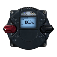
Indicates that all further settings are configured via the SMARTCON interface after initial actuator pre-setup.
Emphasizes the critical need to verify torque settings and teach the end positions.
Explains how user levels and permissions affect parameter access and editing.
Describes the process for setting the actuator's end positions using the SMARTCON control unit.
Details the steps for setting the OPEN end limit through the control unit's menu interface.
Instructs on setting the CLOSE end limit using the corresponding menu item.
Covers the procedure for setting end positions when actuators utilize travel switches.
Explains the method for setting end positions with a roller-type counter mechanism.
Warns that maintenance on open actuators requires de-energized state and prohibits reconnection during work.
States that all electrical system work must be performed by qualified electricians according to regulations.
Mandates that work on opened devices must be in a de-energized state and prohibits switching on during the process.
Advises waiting a specific time after switching off before opening covers on explosion-proof actuators.
Identifies the main fuse (F1) located upstream of the electronic reversing starter.
Identifies the control fuse (F2) positioned before the control transformer.
Instructs users to provide the serial number when ordering replacement parts.
Recommends specific lubricants for the main casing based on operating temperature ranges.
Specifies lubricant for the main casing at -35°C to +100°C, referencing DIN 51826.
Recommends lubricating oil CLP DIN 51517-3 for application temperatures between -50°C and +100°C.
Recommends lubricating oil CLP DIN 51517-3 for application temperatures between -60°C and +100°C.
Recommends lubricating grease DIN 51825 for spur gears in AB8-AB80 actuators.
Recommends lubricating grease DIN 51825 for output drives and failsafe units.
Recommends lubricating grease (or spray) DIN 58396 for precision components.
Details how to calculate lubricant maintenance intervals by applying reduction factors to operational conditions.
Warns that calculated maintenance intervals are not applicable to output type A or linear/spindle actuators.
Provides a table listing the specific quantities of lubricant needed for various actuator types and components.
Advises contacting SCHIEBEL for assistance with any assembly or adjustment issues encountered on-site.
Recommends employing qualified personnel for assembly and offers company-based training services.
Identifies the manufacturer and its address for the declaration.
Introduces the declaration concerning electric actuators and their optional additional components.
Lists the core requirements of the Machinery Directive (2006/42/EC) that have been met.
Enlists the European harmonized standards that have been applied to the machinery.
Confirms the preparation of relevant technical documentation as stipulated by Annex VII, Part B.
Designates the authorized individual responsible for preparing the technical documentation.
Stipulates that the machinery cannot be used until the final integrated machinery complies with the Machinery Directive.
Confirms that the electric actuators, as partly completed machinery, align with relevant EU directives.
Specifies the directives covered: Electromagnetic Compatibility (EMV) and Low Voltage.
Identifies the producer of the equipment.
States the manufacturer's name and address.
Formally confirms that the equipment meets specified EC-directive requirements.
Lists the types of electric actuators and control units covered by this declaration.
Specifies the actuator series and control unit models included in the declaration.
Declares that the equipment satisfies the requirements of the specified EC-directive.
Cites the EC-directive 2014/30/EU concerning Electromagnetic Compatibility.
Mentions that directive fulfillment is demonstrated via operating instructions and specific standards.
Lists the harmonized standard EN 61000-6-2:2005 for EMV compliance.
Lists the harmonized standard EN 61000-6-3:2007-01 + A1:2011-03 for EMV compliance.
Confirms the equipment's consistency with an additional EC-directive.
Cites the EC-directive 2014/35/EU concerning Low Voltage.
Mentions that directive fulfillment is demonstrated via operating instructions and specific standards.
Lists the harmonized standard IEC 60204-1:2005 + A1:2008 for Low Voltage compliance.
Lists the harmonized standard EN 60529:1991 + A1:2000 for Low Voltage compliance.
Specifies the EU directives covered: ATEX (Ex), EMV, and Low Voltage.
Identifies the producer of the equipment.
States the manufacturer's name and address.
Confirms that the described equipment meets the requirements of the EC-directive.
Cites the EC-directive 2014/34/EU for equipment in potentially explosive atmospheres.
Confirms compliance with harmonized standards applicable at the declaration date.
Lists the harmonized standard EN60079-0:2014 for general requirements in explosive atmospheres.
Lists the harmonized standard EN60079-1:2014 for flameproof enclosures.
Lists the harmonized standard EN60079-7:2016 for increased safety measures.
Lists the harmonized standard EN60079-11:2012 for intrinsic safety.
Mentions the notified bodies that have certified the equipment's design conformity.
Identifies notified body FTZU and the types of certificates issued.
Identifies notified body TÜV Austria and the types of certificates issued.
Details specifications for binary outputs, including count, voltage, and current limits.
Provides specifications for binary inputs, including count, voltage, and current consumption.
Describes specifications for analog inputs, including current range, resolution, and accuracy.
Details specifications for the analog output, including current range, resolution, and accuracy.
Specifies voltage ranges and current consumption for auxiliary voltage input/output.
Explains the function and assignments of the mechanical reversing starter.
Describes the optional electronic reversing starter and its advantages over mechanical starters.
Presents load capacity diagrams and service life data for micro switches.
Lists possible voltage ranges and frequency for the SMARTCON control unit power supply.
Details connection options for power and control signals based on actuator size and version.
Lists miscellaneous technical data like ambient temperature, protection class, and color options.
| Brand | SCHIEBEL |
|---|---|
| Model | AB3 |
| Category | Controller |
| Language | English |