15 Technical data
Operating Instructions for Actuators Type AB with Control Unit
OM-ENGLISH-ABCSC.V1.2-16xx-V2.02-2023.04.27
Resolution: . . . . . . . . . . . . . . . . . . . . . . . . . . . . . . . . . . . . . . . . . . . . . . . . . . . . .12 bit
Accuracy: . . . . . . . . . . . . . . . . . . . . . . . . . . . . . . . . . . . . . . . . . . . . . . . . . . . . . . 0.5%
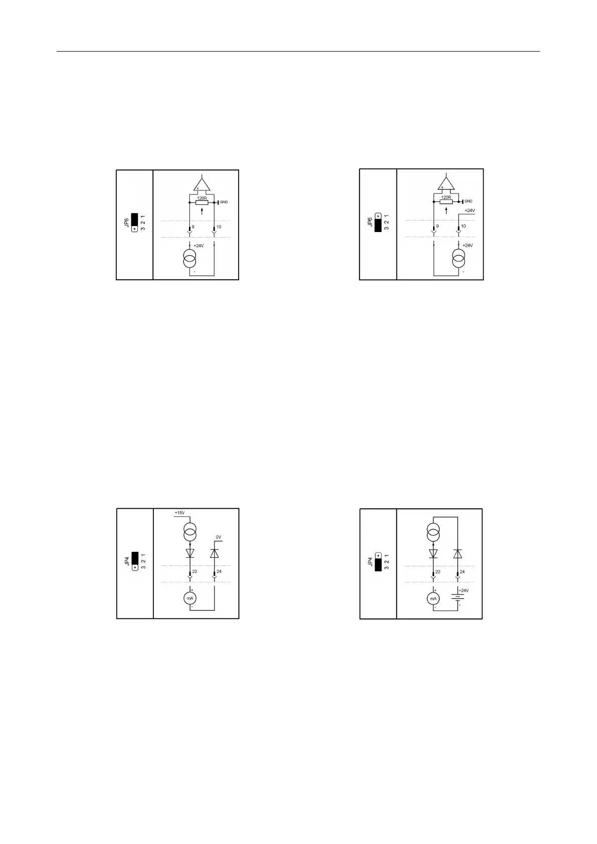
Input resistance: . . . . . . . . . . . . . . . . . . . . . . . . . . . . . . . . . . . . . . . . . . . . . . . 120 Ω
Jumper JP6 can be used to switch analog input 2 from a passive input (default) to an input with internal 24 V
power supply (for 4. . . 20 mA, two-wire transmitters).
Figure 63: Passive input (default) Figure 64: Input with internal suppy (active input)
NOTE: The analog input 2 is referenced to common of the electronic system and the auxiliary power supply
(see section 15.5).
15.4 Analog output
Current range: . . . . . . . . . . . . . . . . . . . . . . . . . . . . . . . . . . . . . . . . . . . . . . . . . 0. . . 20.8 mA
Resolution: . . . . . . . . . . . . . . . . . . . . . . . . . . . . . . . . . . . . . . . . . . . . . . . . . . . . .12 bit
Accuracy: . . . . . . . . . . . . . . . . . . . . . . . . . . . . . . . . . . . . . . . . . . . . . . . . . . . . . . 0.5%
Max load: . . . . . . . . . . . . . . . . . . . . . . . . . . . . . . . . . . . . . . . . . . . . . . . . . . . . . . 600 Ω
The analog output is galvanically isolated from the rest of the electronic system.
Jumper JP4 can be used to switch the analog output from an active power source (default) to a current sink,
allowing the output to simulate a 4.. . 20 mA, two-wire transmitter.
Figure 65: Current source Figure 66: Current sink
Ground potential is the potential of the control unit and the auxiliary supply (see chapter 15.5).
15.5 Auxiliary voltage input and output
Input voltage range (auxiliary voltage input): . . . . . . . . . . . . . . . . . . . . 20. . . 30 VDC
Maximum current consumption (auxiliary voltage input): . . . . . . . . 500 mA
Maximum current consumption in power-save mode . . . . . . . . . . . . 120 mA
(auxiliary voltage input):
Output voltage (auxiliary voltage output): . . . . . . . . . . . . . . . . . . . . . . . typ. 23 V
Maximum output current (auxiliary voltage output): . . . . . . . . . . . . . .200 mA
36