15 Technical data
Operating Instructions for Actuators Type AB with Control Unit
OM-ENGLISH-ABCSC.V1.2-16xx-V2.02-2023.04.27
CAUTION: These values apply to utilization category AC-3
(switching off during motor run) and not to utilization category
AC-4 (inching)! With AC-4, stressing by the high breaking current
is substantially higher, so the service life is considerably shorter.
For this reason, inching (switch-off during motor start-up) should
be avoided with mechanical reversing contactors.
15.7 Electronical reversing starter
Optionally, the motor of the actuator is controlled by an electronic reversing contactor (thyristors). The elec-
tronic reversing contactor switches two of the three motor phases. The control of the two directions of rotation
is locked by hardware in the electronic reversing contactor. Compared to conventional mechanical contactors
there is no mechanical wear through contact burning; in case of electronic reversing starters this feature in-
creases the life and reliability of modulating actuators with high switching frequency.
CAUTION: The third phase is not switched in the electronic
reversing contactor and is therefore constantly on the motor
winding.
voltage range: . . . . . . . . . . . . . . . . . . . . . . . . . . . . . . . . . . . . . . . . . . . . . . . . . . 48. . . 480Vrms
current range: . . . . . . . . . . . . . . . . . . . . . . . . . . . . . . . . . . . . . . . . . . . . . . . . . . 0,1. . . 50Arms
transient overvoltage: . . . . . . . . . . . . . . . . . . . . . . . . . . . . . . . . . . . . . . . . . . 720Vpk
max. I
2
t of the fuse: . . . . . . . . . . . . . . . . . . . . . . . . . . . . . . . . . . . . . . . . . . . . 2320A
2
s
lock time when changing direction:: . . . . . . . . . . . . . . . . . . . . . . . . . . . . .min. 100msec
15.8 Micro switch
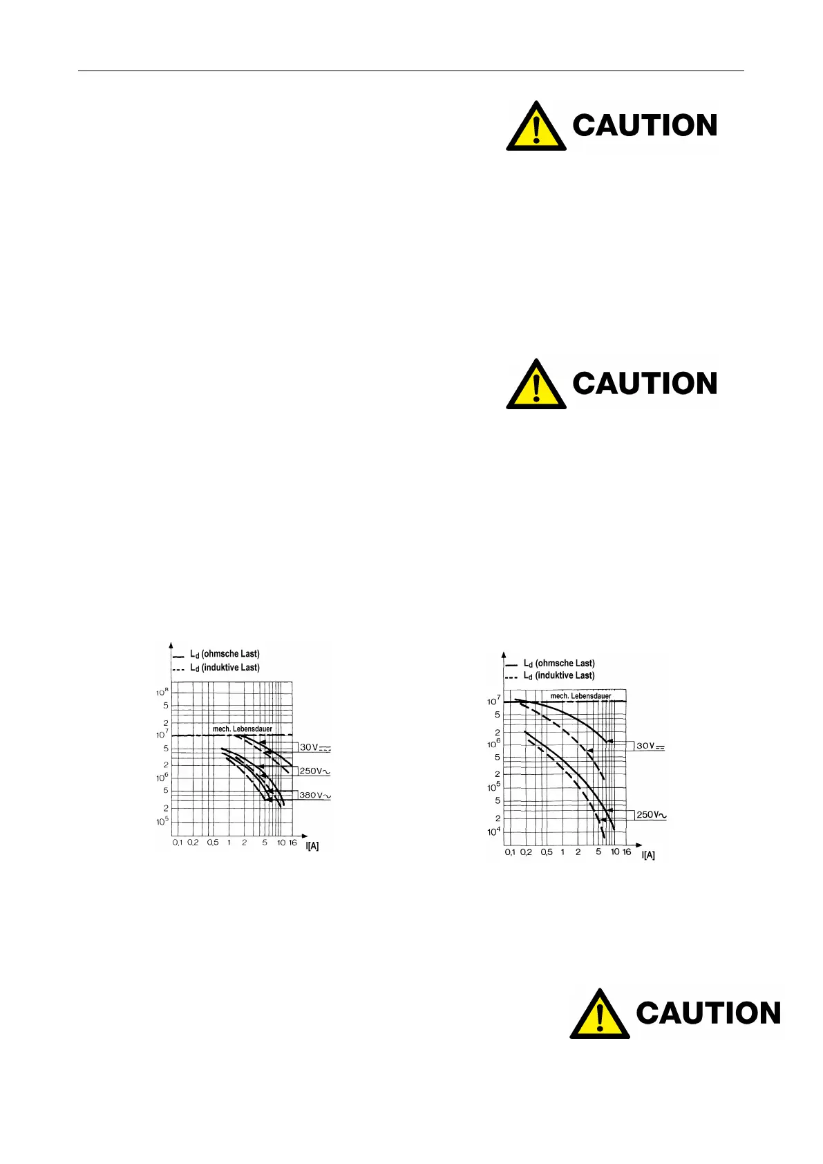
Standard switch
Figure 68: Load capacity diagram (83106)
Mech. serice life L
d
. . . . . . . . . . . . 10
7
switching cycles
Permissible ambient temp . . . . . . -20...+85°C
Special models . . . . . . . . . . . . . . . . . -40...+125°C
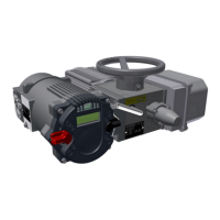
Flashing switch and Explosion-proof micro-switch:
Figure 69: Load capacity diagram (83133)
Mech. service life L
d
. . . . . . . . . . . 10
7
switching cycles
Permissible ambient temp . . . . . . -20...+125°C
For the ohmic load capacity, cosφ=1 shall apply. The inductive load capacity given is cosφ=0,8 and/or
L/R=5ms.
CAUTION: The maximum switching current for micro switches
with gold-plated contacts is 40 mA a voltage of 24 V (ohmic load).
If switching currents are too high, the goldplating will be destroyed.
38