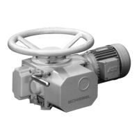
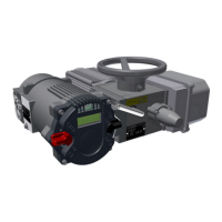
4 Installation Instructions
Operating Instructions for Actuators Type AB with Control Unit
OM-ENGLISH-ABCSC.V1.2-16xx-V2.02-2023.04.27
• Tighten the fastening screws crosswise (torque acc. below table).
size torque [Nm] for screws 8.8
M6 10
M8 25
M10 48
M12 84
M16 206
M20 415
CAUTION: For output type A (unbored threaded bushing), you
must sufficiently lubricate both needle bearings in the output form
after processing and cleaning the spindle nut. For this purpose,
use the optional SCHIEBEL grease lubricant or a grease lubricant
according to our recommendation (section 10, page 25).
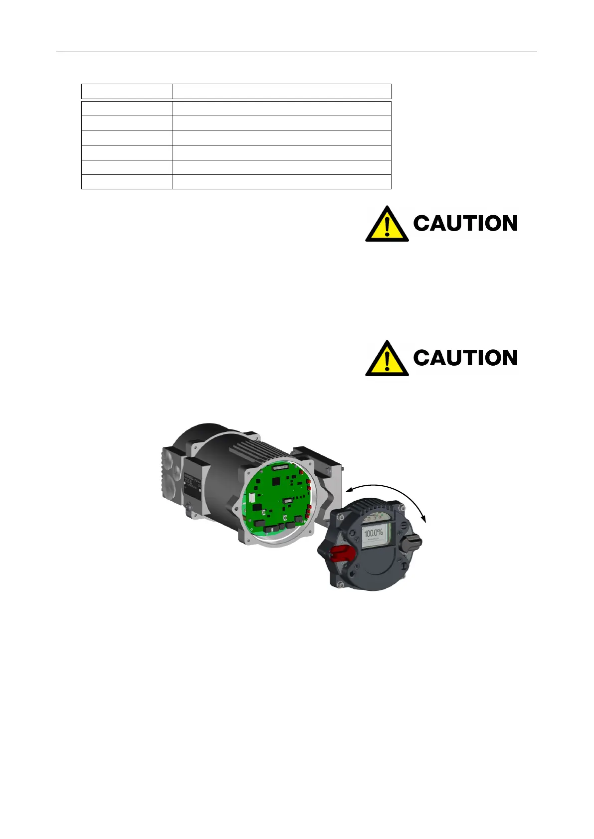
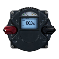
4.2 Mounting position of the control unit
The control unit can be rotated in 90° steps.
CAUTION: During installation, the position of the control unit in
relation to direct sunlight must be observed. It is recommended to
protect the unit from direct sunlight (roof, installation position) to
avoid possible malfunctions.
Figure 12
• Disconnect the actuator and control system from the power supply.
• To prevent damage to the electronic components, both the control system and the person have to be
earthed!
• Undo the bolts for the interface surface and carefully remove the service cover.
• Turn service cover to new position and put back on.
– Ensure correct position of the O-ring
– Turn service cover by max. of 180°.
– Put service cover on carefully so that no cables get wedged in.
12