4 Installation Instructions
Operating Instructions for Actuators Type AB with Control Unit
OM-ENGLISH-ABCSC.V1.2-16xx-V2.02-2023.04.27
made by an additional plug (see Figure 14), both plugs aer with screw connection.
Figure 14: size 2 with the additional plug, 1. . . M40x1,5
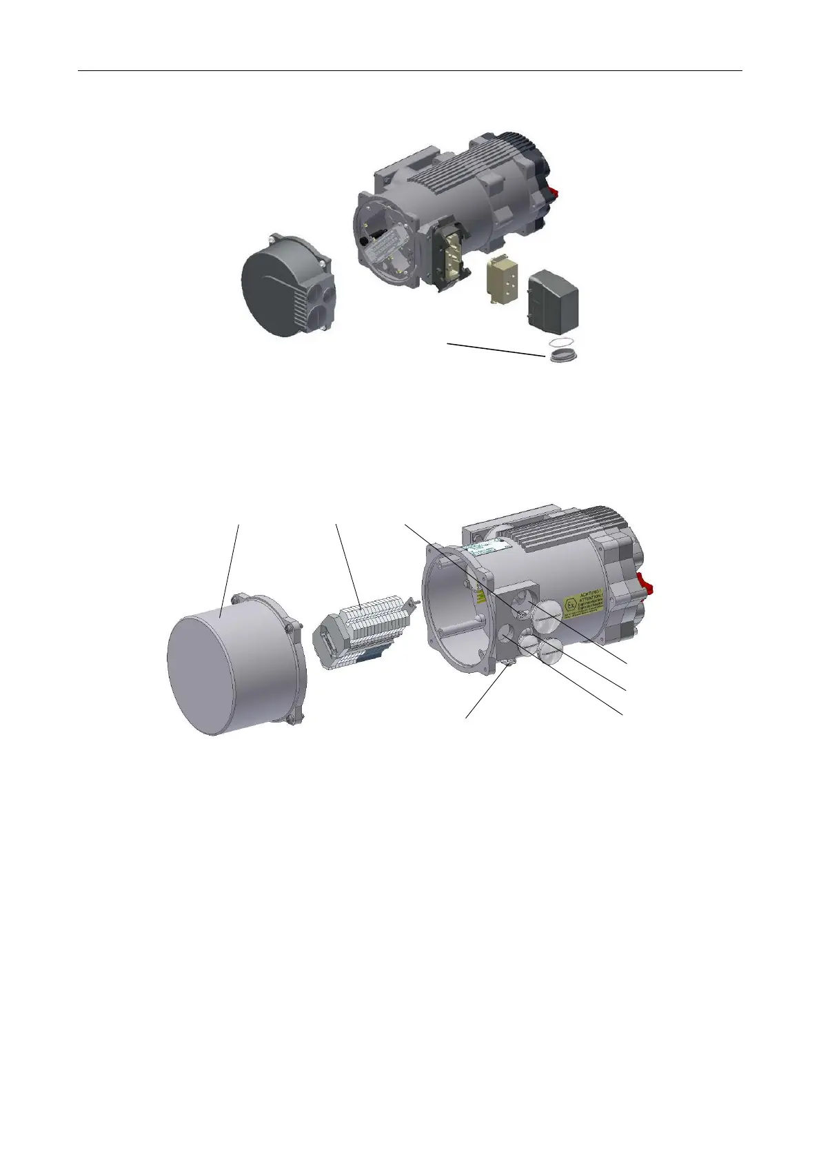
• Explosion-proof actuators or on special request the connection will be mady via terminals (see Figure
15).
Figure 15: 1. . . connection plug housing, 2. . . terminal strip, 3. . . inside ground connection, 4. . . metallic ca-
ble glands (closed with blind screw connections at delivery) M40x1,5, 5. . . M32x1,5, 6. . . M25x1,5,
7. . . outside ground connection
3 phase power is applied in positive turning direction of the electric field on the connectors L1, L2, L3 according
the wiring diagram. Before starting the actuator the turning direction of the electric field should be checked.
NOTE: If phase sequence of the three phase power supply system is wrong the integrated phase sequence
monitoring generates an error and the actuator is blocked. (see Operating Instructions for SMARTCON Control
Units)
If a reverse rotation of the actuator (ccw) is needed, the rotation direction must be changed in the control
unit (see Operating Instructions for SMARTCON Control Units).
NOTE: Please also note the information about the installation of an external motor protection circuit breaker -
see section 2.7.3, page 8.
14