ExMax- 30 -BF ►
ExMax- 50 -BF ►
ExMax- 60 -BF ►
30 Nm
50 Nm
60 Nm
▼
40 s/90° ►
60 s/90° ►
90 s/90° ►
120 s/90° ►
150 s/90° ►
00
01
02
03
04
05
06
07
08
09
ExBoxExPro-TT
a b
+
~
+
~
−
~
−
~
PE
PE
1
1
2
2
3
3
4
4
24...240 VAC/DC
24...240 VAC/DC
PA
PA5
5
8
8
6
6
7
7
9
9
10
10
< 5°
< 5°
> 85°
> 85°
1
1
2
2
°C
°C
ExPro-TT
ExPro-TT
U < 90 V AC/DC 2 AT 10 AT
U > 90 V AC/DC 5 AT 10 AT
U < 90 V AC/DC 2 AT 10 AT
U > 90 V AC/DC 5 AT 10 AT
S
T
U
o
= 5,88 V
I
o
= 24,75 mA
P
o
= 37 mW
C
i
= 0
L
i
= 0
IIC IIB IIA
L
o
50 mH 50 mH 50 mH
C
o
43 μF 1000 μF 1000 μF
www.schischek.com
Schischek GmbH Germany, Muehlsteig 45, Gewerbegebiet Sued 5, 90579 Langenzenn, Tel. +49 9101 9081-0, Fax +49 9101 9081-77, E-Mail info-de@schischek.com
ExMax-M-BF_en
V04 – 14-Jan-2019
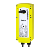
ExMax-...-BF
Special option ... -CTM ... -VAM
Electrical connection Parameters, adjustments and failure indication
Parameter selection
Functions, adjustments and parameters
Type
Running times Position of switch (S)
Torques
Example:
ExMax-30-BF
Requested parameter:
Torque 30 Nm
Motor running time 90 s/90°
Result:
Switch position 02
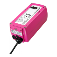
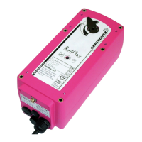
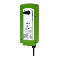
All actuators are equipped with a universal supply unit working at a voltage range from
24...240 VAC/DC. The supply unit is self adjusting to the connected voltage!
The safety operation of the spring return function works if the supply voltage is cut.
For electrical connection inside hazardous areas an Ex-e terminal box, certificated in acc.
with ATEX is required (e.g. ExBox).
An over-current protection fuse < 10 A has to be provided by installer.
Note: the initial current is appr. 2 A for 1 second.
Integrated auxiliary switches signal the rotation angle’s position. U
min
and I
min
change once
the switches were operated with higher voltage or current.
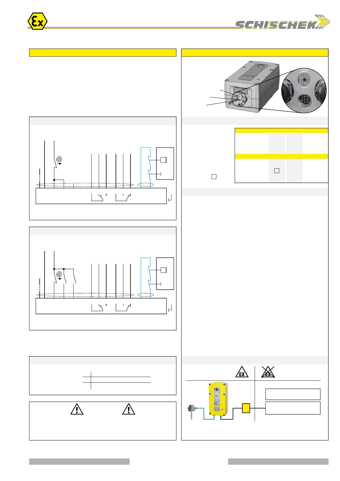
Installation
Switch – Push button – Lamp
for adjustment
(behind the blanking plug)
10-position switch (S)
3-colour LED
Push button (T)
Supply *
24...240 VAC/DC ± 10 %
* electrical wiring see diagrams
Ex-i intrinsic safe data – for temperature trigger ExPro-TT T 1.0
Ex area –
zone 1, 2, 21, 22
Safe area
Auxiliary switches *
see Technical data
On-off (1-wire) – spring return + Ex-i tripping circuit SB 7.2
On-off / 3-pos. – spring return + Ex-i tripping circuit SB 7.3
Ex-i tripping circuit for
ExPro-TT-... safety
temperature trigger
Test
button
Test
button
Attention!
At 1-wire control
mode the heater
does not work
in case of
open contact.
Ex-i tripping circuit for
ExPro-TT-... safety
temperature trigger
Integrated auxiliary switches,
Grid fuse-protection recommended.
min. max.
Integrated auxiliary switches,
Grid fuse-protection recommended.
min. max.
A) Self adjustment of angle of rotation
Turn switch (S) to position 02. Press button (T) for a minimum of 3 seconds. The
actuator drives to both end positions and detects the blocking positions. The LED
flashes GREEN during adjustment.
The adjustment takes about 60 seconds (30 sec. “On”, 30 sec. “Off”).
B) Selecting motor running time and torque
Adjust parameters only if actuator is in idle state or without applied potential.
Turn switch (S) to the position required for the intended operation acc. to table
above. The selected parameters will be carried out at the actuator’s next operation.
C) Function of the ExPro-TT-... in the Ex-i tripping circuit
When the ...Pro-TT’s tripping circuit is opened the actuator runs into its end position
with spring return.
D) Additional information for control in 3-pos. operation
a closed, b open = direction I a and b closed = motor doesn’t work
b closed, a open = direction II a and b open = motor doesn’t work
The rotation direction (I and II) depends on left/right mounting of the actuator to the
damper. To reverse the rotation direction (by motor) exchange the electrical wiring
of terminal 3 and 4.
Attention
During commissioning apply a self adjustment drive.
Regard duty cycle at motor running times!
Never use spring return actuators without external load.
3 / 4