EasyManua.ls Logo

Schlage L9000 Series User Manual

Schlage L9000 Series
24 pages
To Next Page IconTo Next Page
Page #1 background imageLoading...
Page #1 background image
*P516-909*
P516-909
Indicator trim is available for either
the inside or outside of the door
on allowable functions.
Non-indicator trim is furnished on
the opposite side of the door.
Conrm desired placement
(inside or outside) before
installation.
The L9000 lock with
indicator is not intended for
exterior door applications.
For retrot, see page 9.
Check the door preparation
dimensions with the template
included in the package.
Inside cylinder with
indicator x outside cylinder
with non-indicator shown
OR
OR
Tools for installation:
Not included:Included:
Cylinder
Indicator
options:
Coin turn Thumb turnPrivacy
Non-indicator
options:
Thumb
turn
CylinderCoin turn Privacy
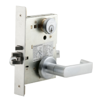
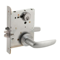
L9000/LV9000 Series Lock with Indicator Sectional Trim Installation Instructions
1 IMPORTANT! Check lock handing before installation.
To change handing:
A. Pull out the latch
and rotate 180°.
B. Remove the lock
handing screw
from one side of
the chassis and
install it on the
opposite side.
The lock handing
screw should
always be on the
interior side of the
door.
L-Series
Actual size
A
B
B\nv"
LV-Series
Actual size
A
B
2 Install lock chassis.
DO NOT FULLY
TIGHTEN CHASSIS
MOUNTING SCREWS
L9000/LV9000
Lock with Indicator

Other manuals for Schlage L9000 Series

Questions and Answers:

Schlage L9000 Series Specifications

General IconGeneral
SeriesL9000
GradeGrade 1
Backset2-3/4"
Door Thickness1-3/4" to 2-1/4"
LockcaseSteel, zinc dichromated for corrosion resistance
LatchboltStainless steel, 3/4" throw
Deadbolt1" throw
HandingReversible
FinishesSatin Chrome, Satin Brass
KeywaySchlage C
StrikeANSI strike standard. Other strike options available.

Summary

Schlage L9000/LV9000 Lock with Indicator Overview

Indicator and Non-Indicator Trim Options

Details on available indicator and non-indicator trim options for door placement.

Pre-Installation Checks and Handing

Crucial steps to check door preparation and adjust lock handing before installation.

Standard Installation Procedures

Install Lock Chassis

Procedure for installing the main lock chassis into the door.

Install Springs, Spindles, and Outside Lever Assembly

Steps for fitting springs, spindles, and assembling the exterior lever.

Install Inside Components and Rose

Procedure for fitting the interior spring cage, mounting plate, and lever.

Prepare Indicator Side of Door

Instructions for preparing the door specifically for the indicator side, including drilling.

Install Outside Indicator Trim

Detailed steps for installing the indicator for various exterior functions (coin turn, cylinder).

Install Inside Indicator Trim

Procedure for installing the interior indicator for cylinder and thumb turn functions.

Final Tightening and Armor Front

Finalizing installation by tightening mounting screws and fitting the armor front.

Indicator Handling and Orientation

Determine and Check Door Handing

Guidance on determining and verifying correct door and indicator handing.

Re-orienting the Indicator Mechanism

Detailed steps to disassemble, reorient, and reassemble the indicator cam and parts.

Indicator Lock Retrofit Instructions

Remove Existing Lock Components

Steps to remove the armor front, cylinders, or thumb turns for retrofitting.

Check Door Preparation for Retrofit

Important check for additional door preparation needed for indicator trim retrofit.

Complete Retrofit Installation

Instructions to complete the indicator trim installation by following specific steps.

Related product manuals