SCHLAGEL, INC. SCHLAGEL, INC.
EDI - V5 CONTROL
WIRING THE CONTROL
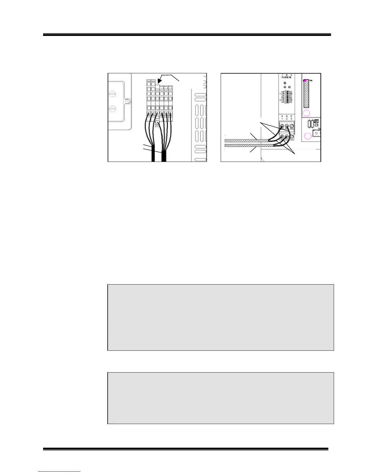
Figure 2 High voltage layout. Figure 3 Sensor connections.
This EDI-V5 control is furnished with an inverter drive, therefore a mechanical
reversing starter is no longer used. Since the inverter can stop the motor in a pre-
determined time, regardless of load, it also eliminates the need for a brake motor.
The installation is further simplified by using a 110 volt supply to power both the
control and the inverter. The inverter converts the this single phase supply to the
220 Volt 3 Phase power needed by the motor.
Caution: The inverter drive has been factory adjusted to function properly with any
EDI distributor. Changes to these adjustments will alter the positioning of the
distributor spout.
Figure 1 shows the field wiring required for the 110 volt supply, sensor and motor
connections. Wire these using the following 3-step procedure.
Panel Power
110 Volt Wiring
Motor Power
230 Volt Wiring
The 110 Volt supply may come from a fused dis
connect or a panel mounted
circuit breaker and the connections are made to the 3 terminal block. This supply
should be rated for 10 Amps and is connected at the ‘cage clamp’ terminals on
the control backplane. .
Refer to Figure 2. The hot and neutral wire
s are connected to either of the gray
colored terminals. Connect the ground wire to the green/yellow terminal.
Step2 – Motor Connections
The 3 phase distributor motor must be wired for 230 volts.
The motor wires, T1, T2 and T3, are connected to the 3 terminals indicated in
figure 2. The ground wire is attached to the green/yellow terminal. Motor rotation
is not important.
Brown
Sensor 1
Sensor 2
Ground
In 110V 1ph
 Loading...