Schmalenberger GmbH + Co. KG
D-72072 Tübingen / Germany
Control box Control NT
Version: 27248 - C
7
Subject to technical changes
Requirement for the function "external sensor button":
• Switch box NT with SW 0.47 and higher (see Nameplate, chapter 6)
• Converter box 3.0 with SW 0.23 and higher
• Converter box 3.0
must be supplied via an external 24V DC voltage source with
Imin=100mA.
Sensor buttons connected to the converter box behave in the same way as the sensor but-
tons connected to the switch box. The total of four buttons that are now available are linked
to each other with a logical OR. If a sensor button is activated, visual feedback of all
connected sensor buttons is given if they light up. The LEDs go out during the blocking
time.
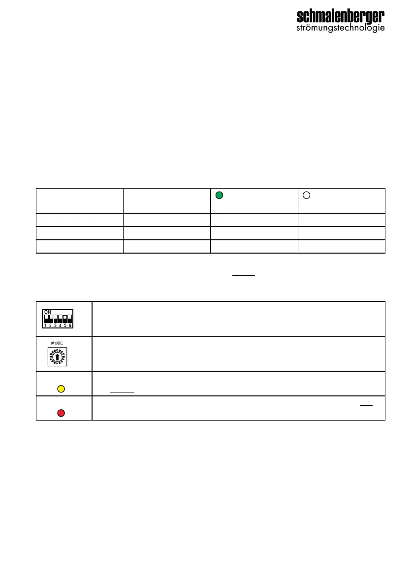
In the connected converter box, the LED display and digital outputs DOUT1 to DOUT3 map
the following status of the switch box:
The status of the digital outputs DOUT1 to DOUT3 is displayed via the green LEDs in the
converter box. The output is then active when the
green LED lights up.
Configuration
The switching device and the converter box are connected via the "BUS" connections with
a two-wire cable. The polarity is arbitrary.
In this case no other bus participants can be connected apart from the converter box.
See connection diagram, section 4.6.4
Also observe the Operator's Manual 27251 "Converter Box 3.0"
2.9.2 Function 2-way valve (BESGO)
see supplement 27265
Switch box
status
Converter box
output
LED
converter box
LED
converter box
Pump ON
DOUT1 Active Inactive
Malfunction
DOUT2 Active Inactive
Enable
DOUT3 Active Inactive
Requirement: SW 0.47 or higher
Master mode: DIP4 ON
Requirement: SW 0.23 or higher
BUS mode: MODE A
BUS-
LED
The communication between converter box and switch box is active when
the
yellow BUS-LED in the converter box lights up.
POWER-
LED
The 24V operating voltage is applied in the converter box when the red
POWER LED lights up. The converter box is ready for operation.
 Loading...