64
Elevator positioning system USP 30 / 100
Interface protocols of
variants USP 30/100 –M24BS / –M24GD / –M24BS
Protocol Pin 10 = 0 V Pin 10 = 24 V
(synchronous, serial interface) RS 422 (asynchronous, serial interface) RS 422
Datasize: – 8 Bit 9 Bit
Length of data package:
24 Bit / 25 Bit 32 Bit
(3 Byte positioning data + 1 Byte diagnostic data)
Position of data: right justified right justified
Data securing: – no Parity
Repetition rate: > 0,2 ms > 4 ms > 3 ms
Transfer rate max. 250 kBaud 19,2 kBaud 38,4 kBaud
Direction of data: MSB first LSB first
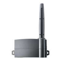
Connection Transmitter
with Connector M12
Pin-no. description type signal
1/2 trigger input trigger signal /power supply transmitter
3/4 trigger-Gnd – ground of trigger signal
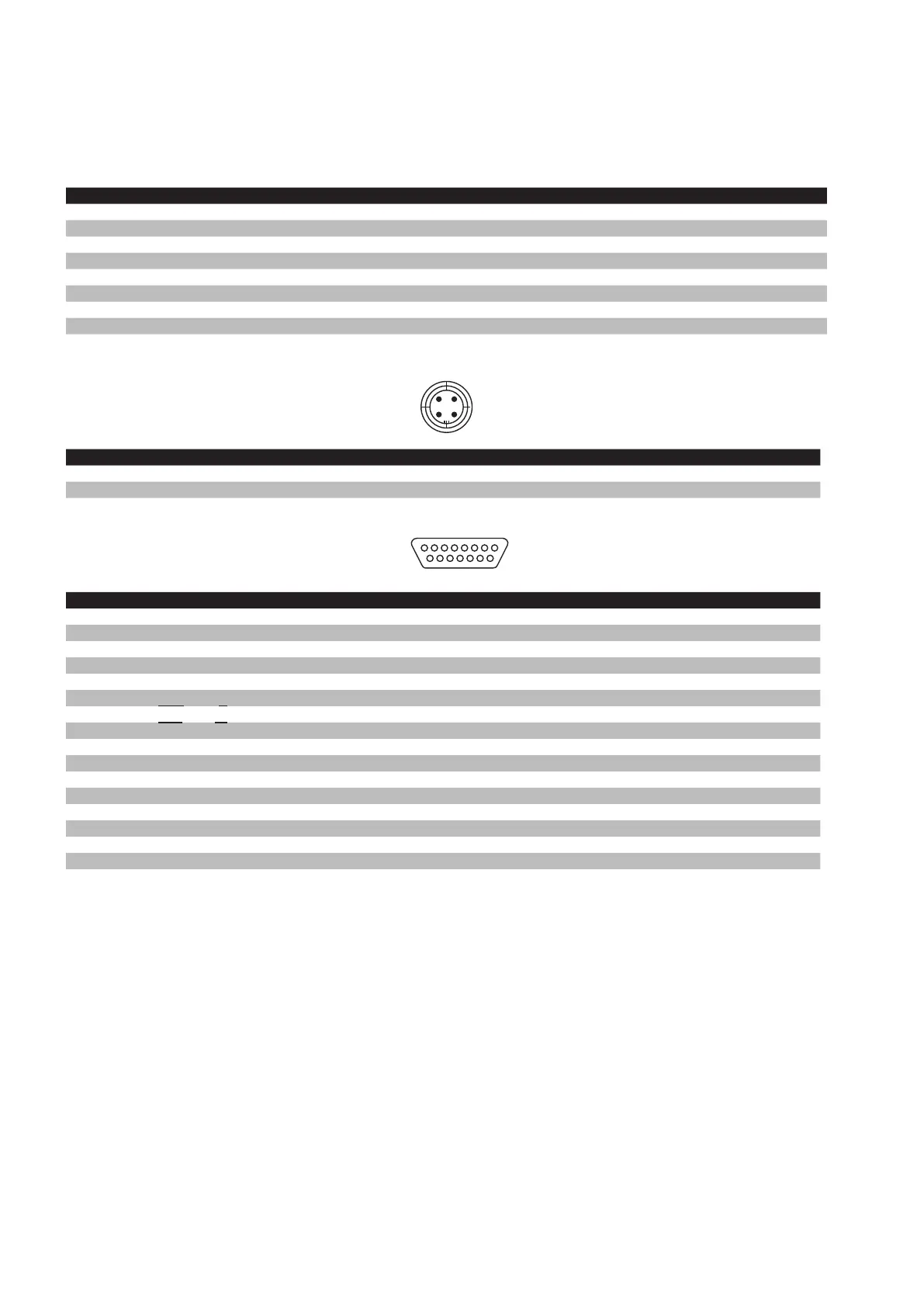
Connection Receiver
with Connector Sub-D, 15-pole
Pin-no. description type signal
1 trigger output trigger signal / power supply transmitter
2 trigger-Gnd – ground of trigger signal
3 reserved
4 reserved
5 Gnd – ground of power supply/
ground of correction sensor *
6 Data (B) / T
X
output asynchronous data signal/SSI data signal
7 CLK (B) / R
X
input SSI-CLK signal
8 CanOpen – Can low
9 U
b
input power supply 24 V
10 Select input 0 V: synchronous serial protocol (SSI)
24 V: asynchronous serial protocol
11 correction sensor input signal correction sensor *
12 reserved
13 Data (A) / T
X
output asynchronous data signal/SSI-data signal
14 CLK (A) / R
X
input SSI-CLK signal
15 CanOpen – Can high
* only USP 100
1 (bn) 2 (wh)
5
USP_Montage_GB.indd 64 18.02.2013 15:39:47
 Loading...