Instructions for Use – SCHMIDT
®
Flow Sensor SS 20.600 Page 22
Figure 4-2
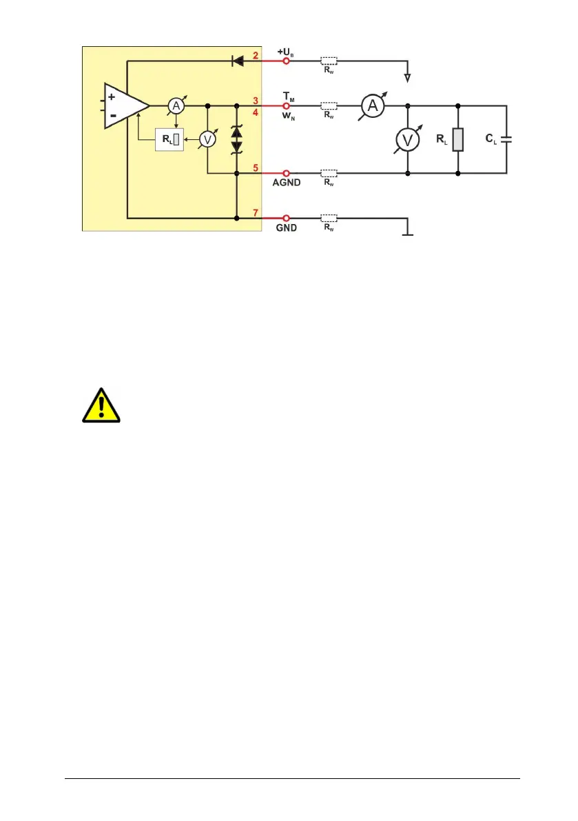
Depending on the value of load resistance R
L
, the electronics switches
between operation as voltage interface (mode: “U”) and current inter-
face (mode: “I”) automatically, hence the designation “Auto-U/I”. The
switching threshold is in range between 500 … 550 Ω (for details refer
to chapter 5 Signaling).
However, in voltage mode a low resistance value may cause significant
voltage losses via the wire resistances R
W
of the connection cable
which can lead to measuring errors (“mass offset”).
For voltage mode, a measuring resistance of at least 10 kΩ is
recommended.
The maximum load capacitance C
L
is 10 nF.
Short circuit mode
In case of a short circuit against the positive rail of the supply voltage
(+U
B
), the signal output is switched off.
In case of a short circuit against the negative rail (GND) of the operating
voltage, the output switches to current mode (R
L
is calculated to 0 )
and provides the required signal current.
If the signal output is connected to +U
B
via a resistance, the value R
L
is
calculated incorrectly and false signal values are caused.