Instructions for Use – SCHMIDT
®
Flow Sensor SS 20.600 Page 20
4 Electrical connection
Make sure that no operating voltage is active during electrical in-
stallation and that the operating voltage cannot be switched on
inadvertently.
The sensor is equipped with a plug-in connector which is firmly integrated
in the housing (pin assignment see Table 4). The connector has the fol-
lowing data:
Number of connection pins: 8 (plus shield connection at the metallic housing)
Type: Male
Fixation of connecting cable: M12 thread (spigot nut at the cable)
Type of protection: IP67 (with screwed cable)
Model: Binder, series 763
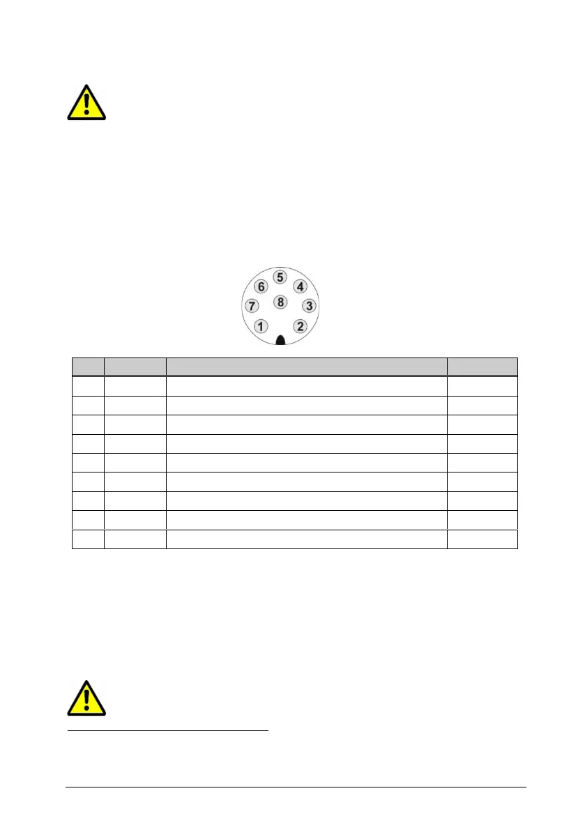
Pin numbering:
View on plug-in connector of sensor
Figure 4-1
Output signal: Flow / volume (digital: PNP)
Operating voltage: 24 V
DC
± 20 %
Output signal: Temperature of medium (Auto-U/I)
Output signal: Flow (Auto-U/I)
Reference potential for analog outputs
Output signal: Flow / volume (relay
13
)
Operating voltage: Ground
Output signal: Flow / volume (relay
13
)
Electromechanical shielding
Table 4
The specified wire colors are valid when one of the SCHMIDT
®
connecting
cables is used (see subchapter Accessories, Table 3).
The analog signals have an own AGND reference potential.
The metal sensor housing is indirectly coupled to GND (with a varistor
,
parallel to 100 nF) and should be connected to a protective potential, e.g.
PE (depending on the shielding concept).
The appropriate protection class III (SELV) respective PELV (ac-
cording EN 50178) has to be considered.
Votage-dependant resistor (VDR); breakthrough voltage 27 V @ 1 mA