Instructions for Use – SCHMIDT
®
Flow Sensor SS 20.600 Page 24
In case of a high capacitive load C
L
, the inrush current impulse
may trigger the quick-reacting short-circuit protection (perma-
nently) although the static current requirement is below the
maximum current I
S,max
. An additional resistor connected in se-
ries to C
L
can eliminate the problem.
Protection against overvoltage.
The pulse output is protected against short-term overvoltage peaks
(e.g. due to ESD or surge) of both polarities by means of a TVS diode
.
Long-term overvoltage destroys the electronics.
Overvoltage can destroy the impulse output.
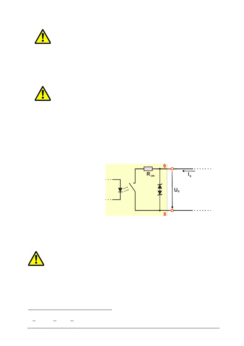
Wiring of impulse output 2 (relay)
The output is realized by a semiconductor relay with the following technical
characteristics:
Technology: SSR (PhotoMOS relay)
Maximum leakage current I
Off,max
: 2 µA
Maximum resistance R
ON
: 16 Ω (typ. 8 )
Maximum switching current I
S
: 50 mA
Maximum switching voltage U
S
: 30 V
DC
/ 21 V
AC,eff
The relay output is protected against short-term overvoltage peaks (e.g.
due to ESD or surge) of both polarities by means of a TVS diode.
Long-term overvoltage destroys the electronics.
Exceeding the specified electrical operating values will lead to ir-
reversible damage.
The output has no protective measures against incorrect wiring.
Transient Voltage Suppressor Diode, breakdown voltage 30 V, pulse 4 kW (8/20 µs)