4 www.scitecinc.com H3000 SERIES USER GUIDE
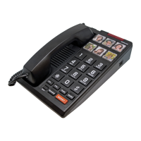
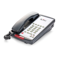
H3000 Single-Line Speakerphone
This telephone user guide details installation,
programming, and operation instructions for the
Scitec H3000 single-line speakerphone. Please
refer to the Scitec website News section and
click on Product Notes for updates to this and
other Scitec products.
Package Contents
• Telephone base unit
• Telephone handset unit
• Coiled handset cord
• Straight line cord
Installation
The telephone is designed for use behind a
registered PABX system. The PABX station port
type must be industry standard analog or POTS.
This telephone cannot be used with digital PABX
station ports. The telephone user or installer must
supply a 2-wire, RJ-11 modular wall jack to
connect this telephone to the PABX system.
To install telephone, first snap supplied coiled
handset cord into the jack on the end of handset.
Then place the handset in its cradle. Connect the
free end of the coiled handset cord to the jack
on left side of the telephone body, marked with
a handset symbol. This jack is closer to the front
of the telephone. Next, take supplied straight
modular cord and insert it into jack on the rear
of telephone. Connect the other end of this cord
to telephone system wall jack. Lift the handset. A
dial tone should be heard.
Assembly
If you will be wall-mounting your phone, it is
best to do the conversion before connecting
the handset and line cords. If you will using the
phone on a desktop, attach the handset.
Attaching the Handset
Connect the supplied coiled handset cord
between the jack on the end of handset and the
jack marked with a handset symbol on the left
side of the telephone base unit. Place the handset
on the telephone base unit or if wall-mounted,
hang it on the desk/wall-mount clip to depress
the hook switch.
Wall-Mounting
1. Located on the top of the telephone above
the speaker grill is the wall/desk mount
clip. Remove this clip by firmly pushing
upward (towards the hookswitch).
2. Flip the clip over (top to bottom) so that
the protruding edge is towards the top of
the phone, and reinsert into cutout. This
protruding edge will hold the handset.
3. Turn the telephone over so the bottom is up,
facing you. Place the telephone on a non-
abrasive surface to prevent scratching.
4. Locate and remove the mounting bracket,
firmly push back and pull up to remove two
of the four retaining tabs.
5. Rotate the mounting bracket 180 degrees
clockwise so that the mounting eyelet on
the bracket is facing in the same direction
as the other mounting eyelet located on the
bottom of the telephone.
6. Insert the top two retaining tabs of the
mounting brackets into the mounting
bracket slots (located near the middle of
the telephone). Then firmly push down to
insert the retaining tabs on the opposite
side of the mounting bracket.
7. Connect a short modular line cord into the
jack on the back of the phone (labeled
TO TEL). Route the line cord through the
line cord channel. Connect the other end