Warning
Grounding should never be connected to a water line,
gas line or lightning rod.
Caution
1.
Power supply and communication
cables should be prepared by the
customer.
2.
Provide a stable power supply which
is not affected by surge or distortion.
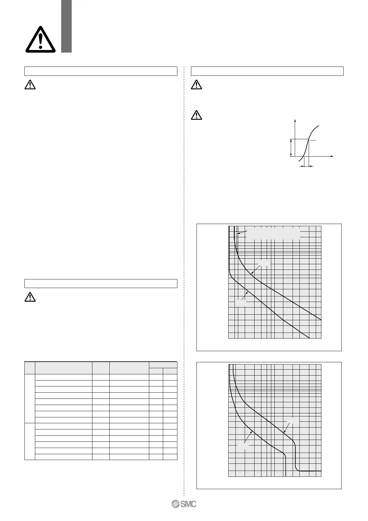
If the voltage increase ratio (dV/dt) at
the zero cross should exceed 40 V/200
μsec., it may result in malfunction.
3.
This product is installed with a breaker with the
following operating characteristics.
For the customer system side (on the upstream side), use a
breaker whose operating time is equal to or longer than the
breaker of this product. If a breaker with shorter operating time
is connected, the customer equipment could be cut off due to
the inrush current of the motor of this product.
dV
dt
=
(For 200 V)
Piping
Caution
1.
The circulating fluid and facility water piping should be prepared
by the customer with consideration of the operating pressure,
temperature, and circulating fluid/facility compatibility.
If the operating performance is not sufficient, the pipings may burst
during operation. Also, the use of corrosive materials such as alu-
minum or iron for fluid contact parts, such as piping, may not only
lead to clogging or leakage in the circulating fluid and facility water
circuits b
ut also refrigerant leakage and other unexpected problems.
Provide protection against corrosion when you use the product.
2.
Select the piping port size which can exceed the rated flow.
For the rated flow, refer to the pump capacity table.
3. When tightening at the drain port of this product,
use a pipe wrench to clamp the connection ports.
4. For the circulating fluid piping connection, install a
drain pan and wastewater collection pit just in case
the circulating fluid may leak.
5. This product series are constant-temperature fluid
circulating machines with built-in tanks.
Do not install equipment on your system side such as pumps
that forcibly return the circulating fluid to the unit. Also, if you at-
tach an external tank that is open to the air, it may become im-
possible to circulate the circulating fluid. Proceed with caution.
6. The facility water flow rate is adjusted automatically
according to the operating conditions.
In addition, the facility water return temperature is
60°C at max.
Circulating Fluid
Caution
1.
Avoid oil or other foreign matter entering the circulating fluid.
2.
When water is used as a circulating fluid, use tap water
that conforms to the appropriate water quality standards.
Use tap water that conforms to the standards shown below (includ-
ing water used for dilution of ethylene glycol aqueous solution).
Tap Water (as a Circulating Fluid) Quality Standards
The Japan Refrigeration and Air Conditioning Industry Association
JRA GL-02-1994 “Cooling water system – Circulation type – Make-up water”
Item Unit Standard value
Influence
Corrosion
Scale generation
Standard item
pH (at 25°C) — 6.0 to 8.0
v v
Electric conductivity (25°C)
[μS/cm]
100
*
1
to 300
*
1
v v
Chloride ion (Cl
–
) [mg/L] 50 or less
v
Sulfuric acid ion (SO
4
2–
) [mg/L] 50 or less
v
Acid consumption amount (at pH4.8)
[mg/L] 50 or less
v
Total hardness [mg/L] 70 or less
v
Calcium hardness (CaCO
3
)
[mg/L] 50 or less
v
Ionic state silica (SiO
2
) [mg/L] 30 or less
v
Reference item
Iron (Fe) [mg/L] 0.3 or less
v v
Copper (Cu) [mg/L] 0.1 or less
v
Sulfide ion (S
2
–
) [mg/L]
Should not be detected
v
Ammonium ion (NH
4
+
) [mg/L] 0.1 or less
v
Residual chlorine (Cl) [mg/L] 0.3 or less
v
Free carbon (CO
2
) [mg/L] 4.0 or less
v
*1 In the case of [MΩ·cm], it will be 0.003 to 0.01.
v
: Factors that have an effect on corrosion or scale generation
Even if the water quality standards are met, complete prevention of corrosion
is not guaranteed.
3.
When deionized (pure) water is used, the electric conductivity should
be 0.5 μS/cm or higher (Electric resistivity: 2 MΩ·cm or lower).
Electrical Wiring
Be sure to read this before handling the products. Refer to the back cover for safety instructions.
For temperature control equipment precautions, refer to the “Handling Precautions for SMC
Products” and the “Operation Manual” on the SMC website: https://www.smcworld.com
HRLE Series
Specific Product Precautions 3
2 h
1 h
30 min
20 min
14 min
10 min
6 min
4 min
2 min
1 min
30 s
20 s
10 s
5 s
2 s
1 s
0.5 s
0.2 s
0.1 s
0.05 s
0.02 s
0.01 s
100 135 200 300 400 500 600 700 1000 1500 2000 3000 4000
Current (% to the capacity of the main breaker of this product)
Operating time
Min.
Max.
HRLE090
2h
1h
30min
10min
4min
2min
1min
30s
20s
10s
5s
2s
1s
0.5s
0.2s
0.1s
0.05s
0.02s
0.01s
100 130 150 200 300 400 500 600 700 1000 1500 2000 3000 4000
Current (% of rated current)
Operating time
Min.
Max.
Operating time per pole
(2-pole type product)
HRLE050
28
A
 Loading...