20
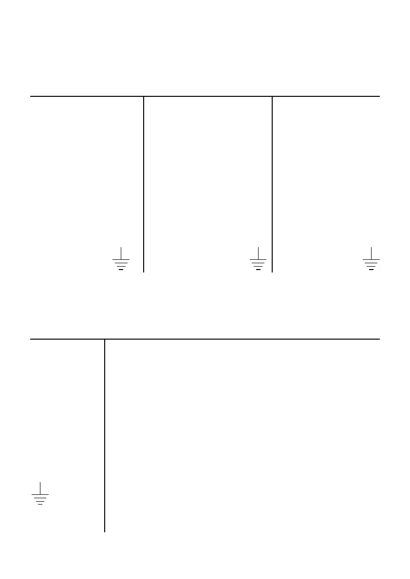
Electrical connections diagram
for motor type FXXX
CABLES IDENTIFICATION
CABLE - N°1 CABLE - N°2 CABLE - N°3
4G4 4G4 4G2.5
BLACK (U) BLACK (Z) BLACK (T)
BLUE (V) BLUE (X) BLACK (T)
BROWN (W) BROWN (Y) BLACK (S)
BLACK (L)*
BLACK (N)*
YELLOW/GREEN YELLOW/GREEN YELLOW/GREEN
DIRECT CONNECTION
U - X = MAINS - 400V
V - Y = MAINS - 400V
W - Z = MAINS - 400V
T - T = Stator thermal protections (to be connected in series to the
contactor coil).
S = Water probe into oil chamber (to be connected to the probe terminal
only if the pump is equipped with a specific control panel).
L - N = Circular 230V single-phase feeding (to be connected only if the
pump is equipped with a cooling jacket).
= Ground
(*) where available.
 Loading...