Page 33
Page 33
G. PUSH BUTTON OPERATION
DURING WATER FILLING PHASE
• Push for more then 2” but less then 5” the
machine enters in Cleaning Mode
• Push for more then 5” the machine by-pass the
Water Filling Phase
DURING FREEZING/HARVEST CYCLE
• Push for more then 5” during the Freezing
cycle the machine goes immediately into
Harvest
• Push for more then 5” during the Harvest cycle
the machine enters immediately in the Freezing
cycle
The length of Harvest is equal to:
•35” if Push Button is activated before -
15°C evaporating temperature LED
activation
•As per Harvest cycle chart, if Push Button
is activated after -15°C evaporating
temperature LED activation (Red LED inside
PC Board ON steady)
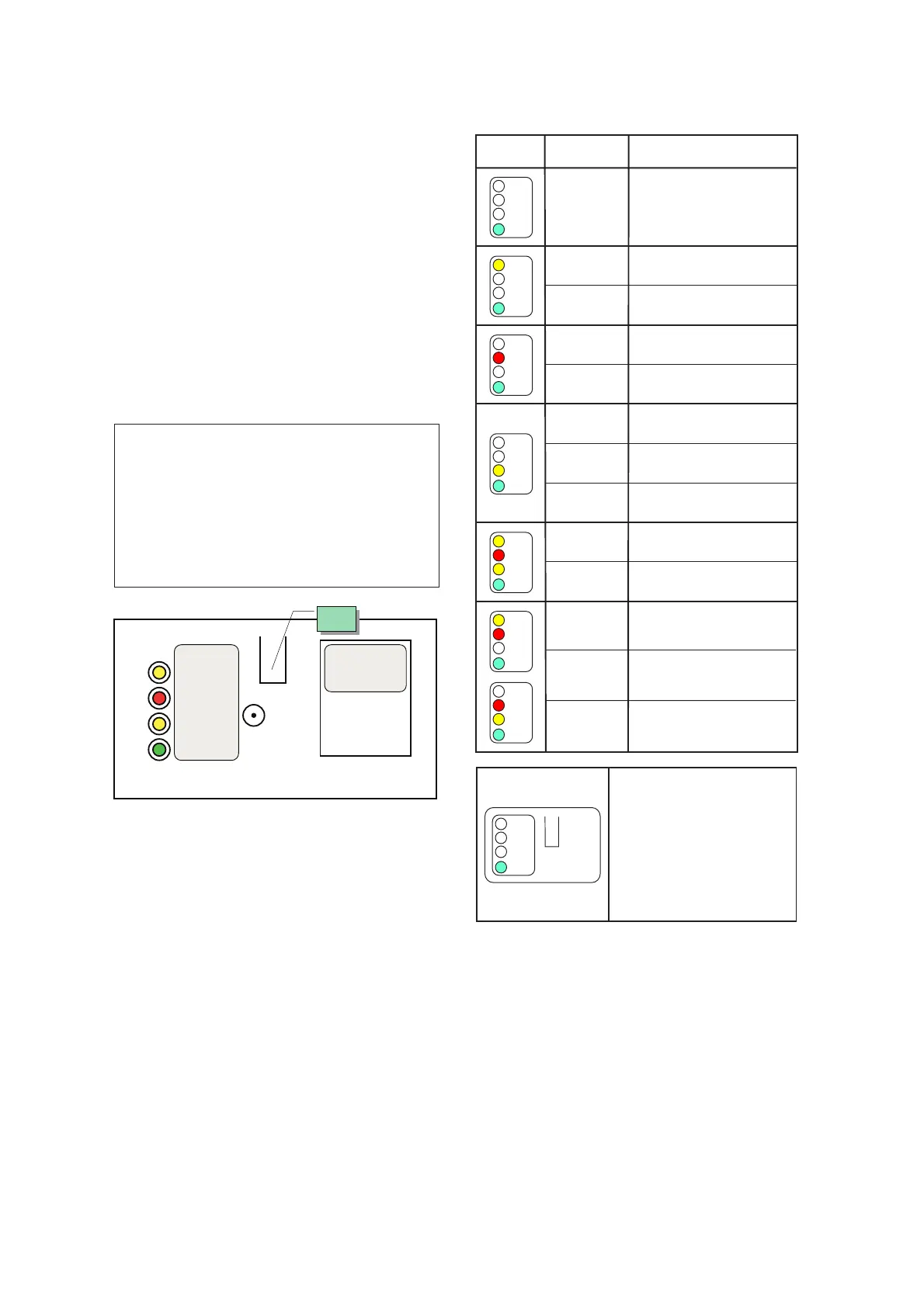
H. LED MEANING
GREEN LED ON
Unit under power
YELLOW BIN FULL LED ON
Unit shut-OFF at storage bin full
YELLOW BIN FULL LED BLINKING
Infrared beam break out
RED ALARM LED ON
Too hi condensing temperature
RED ALARM LED BLINKING
Too hi evaporating temperature
YELLOW FREEZING CYCLE ON
Unit in freezing cycle mode
YELLOW FREEZING LED AND RED ALARM
LED ON
Condenser sensor out of order
YELLOW FREEZING LED AND RED ALARM
LED BLINKING
Evaporator sensor out of order
FREEZING CYCLE
BIN FULL
POWER
TOO HI EVAP TEMP
TOO HI COND TEMP
PUSH
BUTTON
PUSH
BUTTON
LED STATUS
REASON WHY
ON STEADY UNIT UNDER POWER
ON STEADY FREEZING CYCLE
BLINKING
60 MINUTES DELAY AT START UP
JUMPER J3 OUT
ON STEADY
TOO HI DISCHARGE
PRESSURE/TEMP
BLINKING
TOO HI EVAP. TEMP. (> 0C°)
AFTER 15’ FROM START UP
ON STEADY UNIT OFF AT BIN FULL
BLINKING
SLOW
I/R BEAM CUTTED
I/R ON AFTER TRIP OFF AT
BIN FULL
BLINKING
FAST
ON STEADY I/R CALIBRATION DONE
BLINKING
UNIT IN CLEANING MODE OR TRIPPING
OFF AFTER TEST - JUMPER TEST IN
ON STEADY
CONDENSER SENSOR OUT
OF ORDER
BLINKING
EVAPORATOR SENSOR OUT
OF ORDER
BLINKING
ALTERNATIVELY
I/R SENSOR OUT OF ORDER
PUSH
PUSH > 5” DURING WATER FILLING TO
MOVE THE UNIT INTO FREEZING
PUSH > 5” DURING FREEZING
TO MOVE THE UNIT INTO DEFROST
PUSH > 5” DURING DEFROST
TO MOVE THE UNIT INTO FREEZING
PUSH 2” > 5” DURING WATER FILLING
TO MOVE THE UNIT INTO CLEANING
PUSH DURING THE 60 MIN START UP
DELAY TIME TO BY-PASS IT
I. DIP SWITCH
The P.C.BOARD which controls the entire
operation of the ice maker, has a DIP SWITCH
with ten switching keys which allow to set up
the micro processor program in order to extend
or to shorten the length of freezing cycle in relation
to the different model and versions of ice machines.
The DIP SWITCH first four keys setting
determines the length of the 2nd phase of
freezing cycle (controlled by the electronic
timer) as detailed in the table B.
The DIP SWITCH keys 5 & 6 setting determines
the length of the defrost cycle according to the