Do you have a question about the Scout MT-700 Series and is the answer not in the manual?
Provides a general introduction to the MT-700 fleet monitoring system.
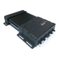
Details the physical components and features of the MT-700 terminal.
Lists all items included in the product package for the user.
Outlines the process and requirements for configuring the device.
Advises on the correct power supply and voltage for the tracker.
Lists the technical parameters and capabilities of the MT-700 system.
Explains the different operational states and transitions of the tracker.
Describes the available input/output ports and their functionalities.
Details how to secure the device against unauthorized access.
Explains methods to secure data transmission using encryption.
Describes the functionality for making voice calls with the device.
Covers sending and receiving SMS commands and notifications.
Guides on installing the SIM card and backup battery.
Covers initial configuration before full installation.
Provides instructions and recommendations for physically installing the device.
Details methods for sealing the device enclosure for protection.
Explains how to connect the GSM and GPS antennas correctly.
Guides on connecting the device to the vehicle's power supply.
Describes how to connect and configure external sensors.
Details settings related to spark-protected environments.
Outlines steps to verify the terminal's functionality after installation.
Explains how to configure the terminal using a local connection.
Details the process for configuring the device remotely.
Covers configuring the terminal via SMS commands.
Describes system-wide settings and their order of application.
Details how to configure and interpret data from internal sensors.
Explains how to set up and manage external device connections via ports.
Specific guidance for configuring digital LLS fuel level sensors.
Illustrates the fundamental wiring for basic operation.
Shows the schematic for connecting an analogue fuel sensor.
Depicts the wiring for a frequency-based fuel sensor.
Provides the connection diagram for digital LLS fuel sensors.
Illustrates how to connect a buzzer to the terminal.
Shows how to connect to vehicle CAN bus protocols.
Details the wiring for an engine speed sensor.
Illustrates the connection for driver identification via iButton.
| Measurement Range | 0 - 700 g |
|---|---|
| Resolution | 0.1 g |
| Readability | 0.1 g |
| Pan Size | ø 130 mm |
| Capacity | 700 g |
| Display | LCD |
| Units of Measurement | Ounce; Troy Ounce; Pennyweight |
| Operating Temperature | 10°C to 30°C |
| Power Supply | Included |