SCS - 926 JR Industrial Drive, Sanford, NC 27332
East: (919) 718-0000 | West: (909) 627-9634 • Website: StaticControl.com
TB-9091 Page 4 of 8
© 2019 DESCO INDUSTRIES INC
Employee Owned
Home / Test Results Screen Memory Recall Menu
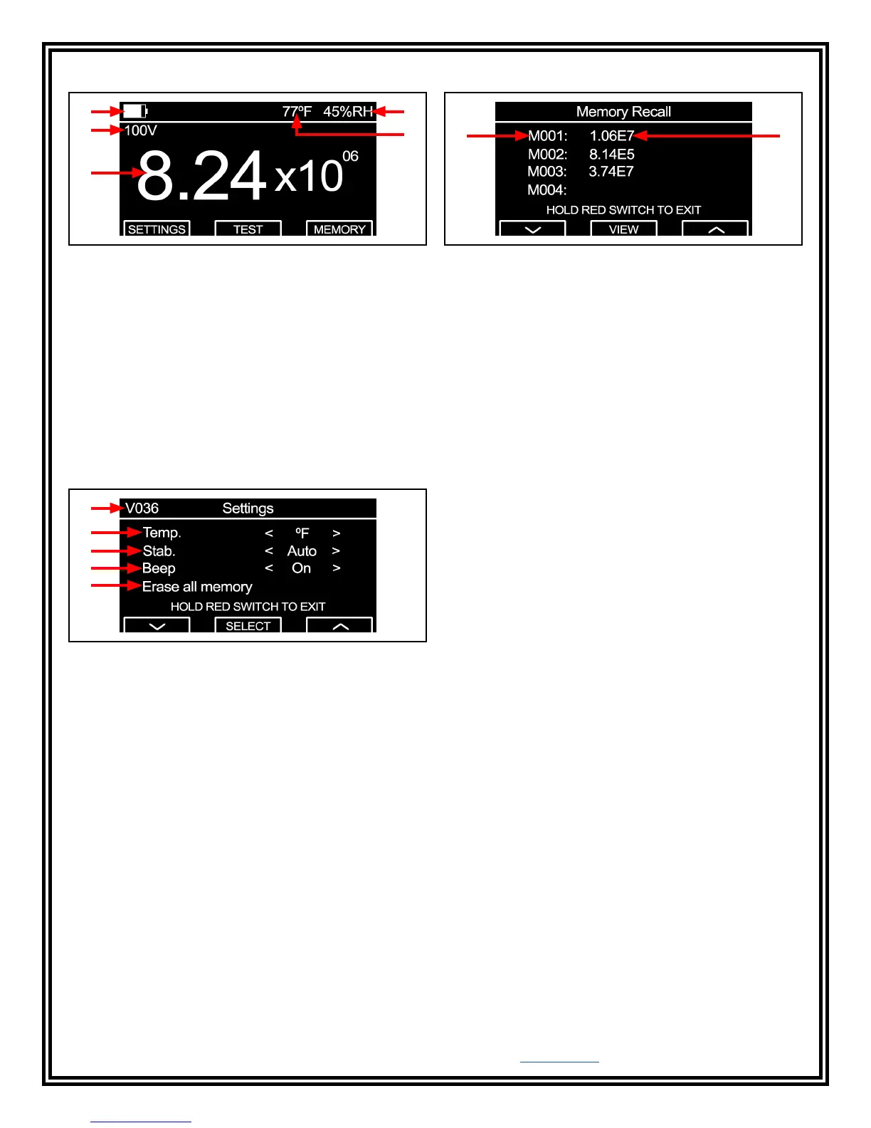
H
J
L
I
K
Figure 5. Home / Test Results screen
H. Battery Life Indicator: Displays the approximate life
of the meter's 4 AA alkaline batteries.
I. Relative Humidity: Displays the relative humidity.
J. Test Voltage: Displays the test voltage used to
complete the measurement.
K. Temperature: Displays the ambient temperature.
L. Resistance Measurement: Displays the resistance
measurement in ohms (Ω).
Settings Menu
M
N
Figure 6. Settings menu
M. Firmware Revision: Displays the meter's firmware
revision.
N. Temperature: Sets the unit of measurement for
temperature to either Fahrenheit (ºF) or Celsius (ºC).
O. Stabilization Mode: Sets the meter's electrification
period setting to either Auto and Fixed Stabilization.
Auto - Enables a 15-second electrification period when
the measured resistance is 1 x 10
10
ohms or greater to
maintain test accuracy.
Fixed - Complies with ANSI/ESD S4.1 and enables a
15-second electrification period when the measured
resistance is 1 x 10
6
ohms or greater.
P. Beep: Enables and disables the audible beep when
the meter's pushbuttons are pressed.
Q. Erase all memory: Erases all stored measurement
transactions saved in the meter's memory.
R S
Figure 7. Settings menu
R. Memory Slot Number: Indicates the memory slot
number.
S. Resistance Measurement: Indicates the resistance
measurement value for the respective memory slot.
Operation
General Guidelines
Use both 5-pound electrodes for Resistance
Point-to-Point (Rtt) measurements.
Use one 5-pound electrode, and connect the black
test lead to ground for Resistance-to-Ground (Rtg)
measurements.
Ensure that the item being measured is electrically
isolated (placed on an insulative surface). The meter will
measure the lowest resistance path.
Minimize crossing the test leads when possible.
When using 5-pound electrodes:
• Place them no closer than 2" from the edge of the
surface being measured.
• Place them no closer than 3" to any groundable
point.
• Place them about 10" apart from each other for Rtt
measurements of a worksurface.
• Place them about 3' apart from each other for Rtt
measurement of a floor.
Preferable electrode placements include:
• Most commonly used area of a surface
• Most worn area
• Center of surface
• Furthest area from a grounded point
If the surface to be measured has sections (i.e. floor
tiles, garment panels), place the 5-pound electrodes on
different sections for Rtt measurements.
Clean the material’s surface for test lab measurements,
but do not clean the surface for materials that are
already installed. Only clean and re-test the installed
material if failure occurs.
O
P
Q
 Loading...