3. Installation
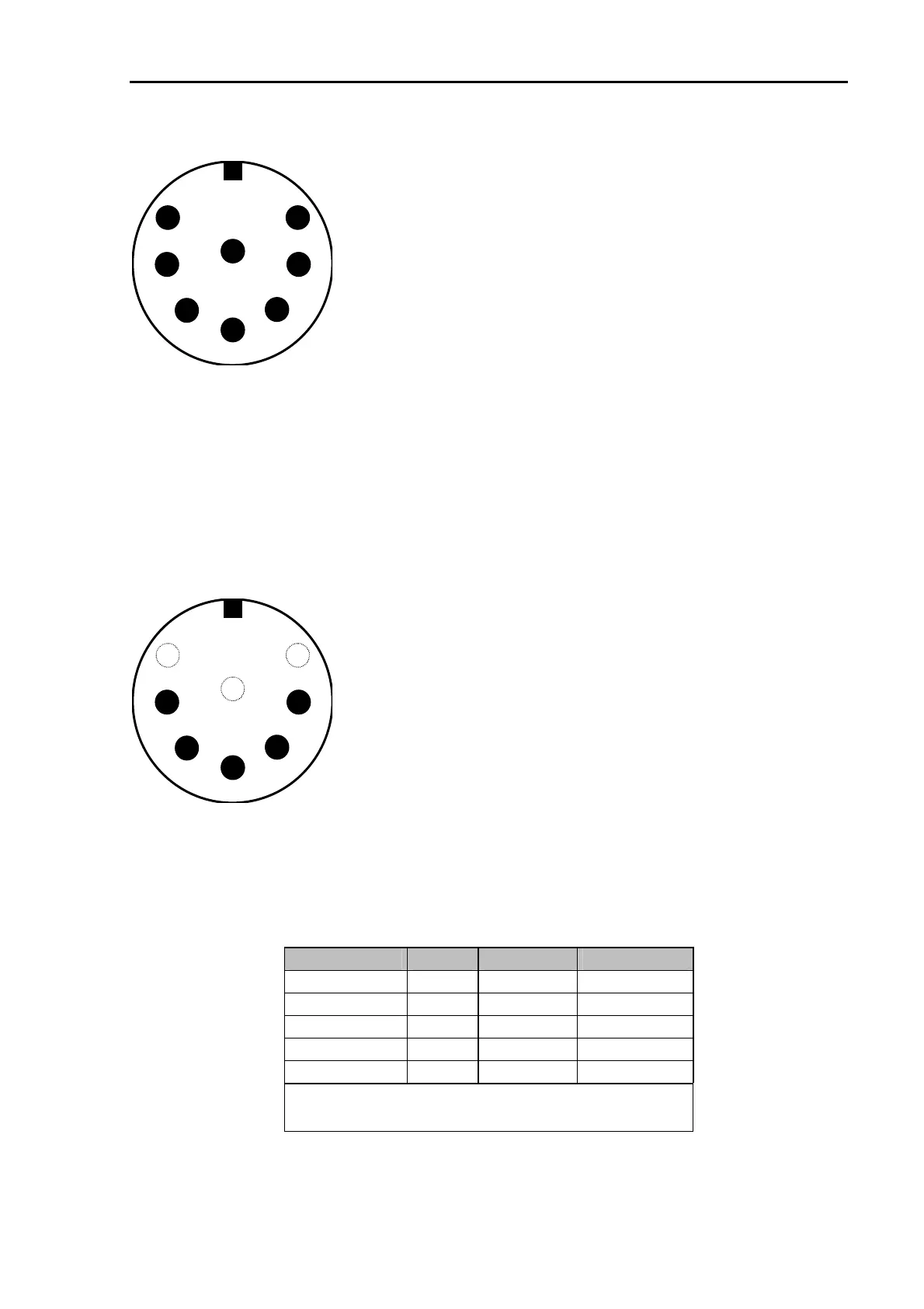
The socket is wired as follows (viewed from the rear of the PTC).
Pin 1: Audio output from the PTC to the transmitter.
Pin 2: Ground.
Pin 3: PTT output. (to transmitter PTT line)
Pin 4: Audio input from the receiver to the PTC.
(loudspeaker or appropriate AUX/ACC socket)
Pin 5: Optional power supply input.
Pin 6: A1 (not PTC-IIex).
Pin 7: FSK output to the transmitter (PTC-IIpro only).
Pin 8: A0 (not PTC-IIex).
8
7
2
6
5
4
3
1
Figure 2: Connection to the transceiver.
NOTE: There are 8 pin plugs with different pin numbering for pin 7 and pin 8. The PTC needs
an 8 pin plug with U-shaped contact footprint. Plugs with circular footprint don’t fit or can
only be attached to the PTC with damaging force! Do not blindly rely on the printed numbers
on the plug. The connections as shown in the manual should be used as reference.
The 8 pin DIN socket is designed in a way that a 5 pin DIN plug (180
°
) may be plugged into it
too. It is possible to use a 5 pin DIN plug if an 8 pin is not available, or the extra functions are
not required.
If a 5 pin DIN plug is used, then the connections are as shown:
8
7
2
6
5
4
3
1
Pin 1: Audio output from the PTC to the transmitter.
Pin 2: Ground.
Pin 3: PTT output (to transmitter PTT line).
Pin 4: Audio input from the receiver to the PTC
(loudspeaker or appropriate AUX socket).
Pin 5: Optional power supply input.
Figure 3: Connections to the transceiver (5 pin DIN).
3.5.1 Connection PTC – ICOM
Most ICOM transceivers that use 8 pin DIN plug (ACC) can be connected this way:
Signal PTC Color ICOM 8 pin
GND PIN 2 white PIN 2
PTT PIN 3 yellow PIN 3
AF-OUT PIN 1 violet PIN 4
AF-IN PIN 4 green PIN 5
POWER PIN 5 blue PIN 7
This cable is available completely assembled.
Refer to chapter 5 on page 52.
Table 3: ICOM 8 pin
39