3. Installation
43
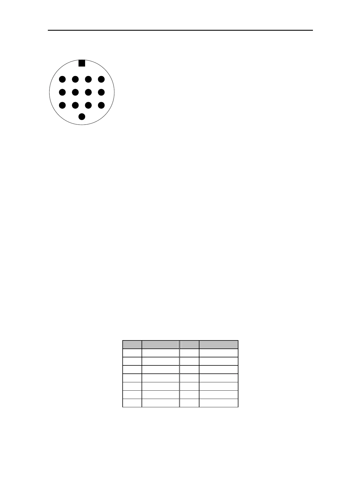
The 13 pin DIN Remote-control socket is connected as follows.
Seen from the back of the PTC-IIpro:
Pin 1: RxD TTL.
Pin 2: RTS V24.
Pin 3: TXD V24.
Pin 4: CTS V24.
Pin 5: CTS TTL.
Pin 6: ICOM.
Pin 7: Not connected.
Pin 8: RxD V24.
Pin 9: TxD TTL.
Pin 10: RTS TTL.
Pin 11: NF out (PTC-IIpro only).
Pin 12: NF GND (PTC-IIpro only).
Pin 13: GND.
243
5678
9
13
1
101112
Figure 4: Transceiver remote-control
TxD TTL
Transmit data from the PTC to the transceiver. TTL level!
RxD TTL
Receive data from the transceiver to the PTC. TTL level!
CTS TTL
Handshake signal from the transceiver to the PTC. TTL level!
RTS TTL
Handshake signal from the PTC to the transceiver. TTL level!
TxD V24
Transmit data from the PTC to the transceiver. V24 level!
RxD V24
Receive data from the transceiver to the PTC. V24 level!
CTS V24
Handshake signal from the transceiver to the PTC. V24 level!
RTS V24
Handshake signal from the PTC to the transceiver. V24 level!
ICOM
Special bi-directional data signal for controlling ICOM equipment.
GND
Ground.
NF out
Audio output signal that can directly be connected to a speaker. This
output is only activated together with the PTC-IIpro´s Audio functions!
(PTC-IIpro only)
NF GND
RETURN for the speaker signal NF out. (PTC-IIpro only)
For many common transceivers completely assembled cables are available, which you find in
our accessories catalog in chapter 5. For all the other transceivers use the attached 13 pin DIN
cable and complete it in the desired way.
PIN Color PIN Color
1 violet 8 red
2 white 9 pink
3 yellow 10 light blue
4 green 11 black/white
5 blue 12 grey
6 black 13 orange
7 brown
Table 11: Cable Colors: 13 pin DIN cable