Scully Signal Company
7
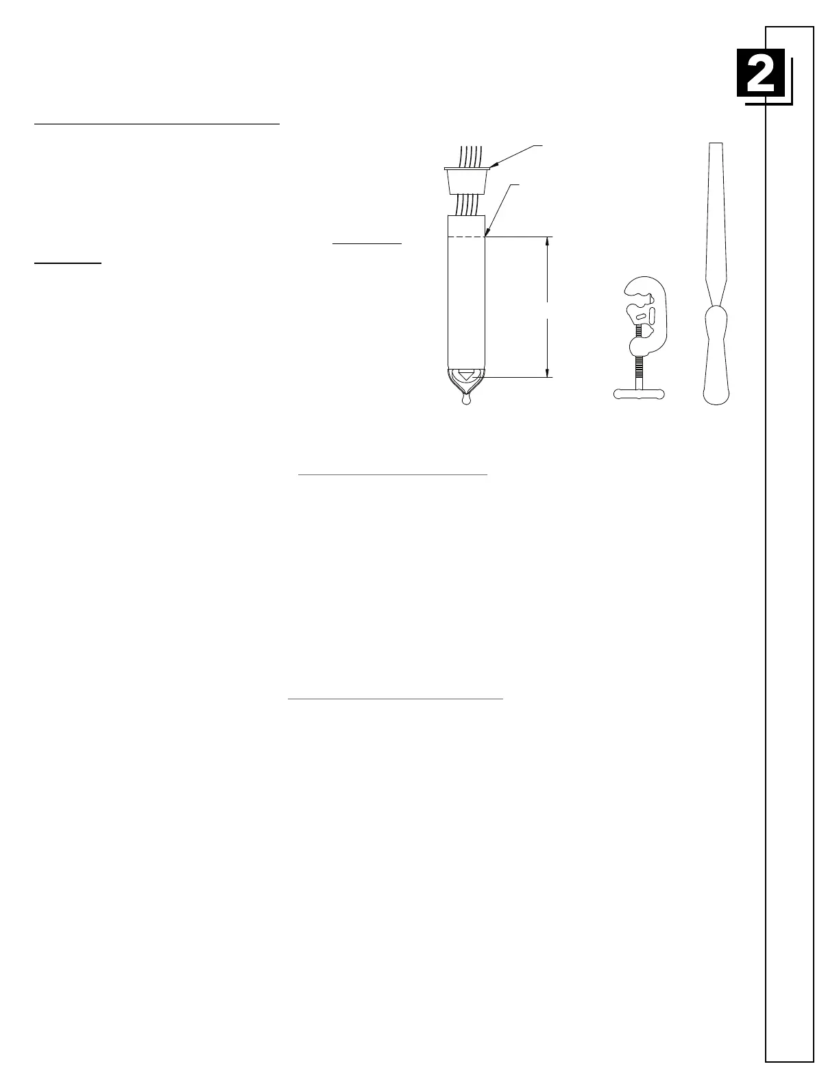
Installation
Shortening the Sensor Shaft
The sensor shaft may be shortened to a minimum of
5 1/2” (140mm) when measured as shown.
A three (3) wheel tubing (pipe) cutter is required.
Grasp the sensor shaft in a padded vise. Do not use an
unpadded vise. Crushing the shaft will damage the
sensor and void the warranty. Using the pipe cutter,
trim the shaft length by carefully cutting away the excess
upper part of the shaft.
File the top edge of the shaft, both inside and outside.
Filing the edge will prevent damage to the sensor holder
O-ring. Insert the wire protective cap into the top of the
sensor shaft to prevent damage to the sensor wires.
LEVEL
SENSING
5.50" (140)
POINT
DO NOT CUT
B
ELOW THIS
PROTECTOR
CAP
LEVEL
SENSING
5.50" (140)
POINT
DO NOT CUT
BELOW THIS
PROTECTOR
CAP
SENSOR REPLACEMENT
It should be noted that a sensor can not be repaired. A damaged or faulty sensor (shaft) must be replaced
with an equivalent Scully sensor and may be mounted into the existing holder. The O-ring inside the
holder may incur damage when removing the faulty sensor. The Scully replacement sensor assembly is
supplied with a replacement O-ring for the holder. After removing the faulty sensor from the holder,
remove the old O-ring from the O-ring groove located in the bore of the holder using an O-ring pick or
other suitable tool. Be careful not to damage the O-ring groove. Apply lubricant, either petroleum jelly or
white grease, to the O-ring before installation. Install the new sensor into the holder per the installation
instructions.
ELECTRICAL INSTALLATION
All connections between the sensor leads and vehicle (truck) wiring are to be made inside the sensor
holder. Use appropriate cable glands for strain relief and watertight installation. If conduit is used, its
connections to the holder must be watertight and free from sharp edges. Unused holes must be plugged
with blanking plugs. The sensor features five wires: Black (ground/earth), Red (power), Green (diagnostic),
Yellow (input signal) and Orange (output signal). The connections should be made using crimp connectors
or other permanent means. It is suggested that electrically non-conductive grease is applied to the
connections to further prevent corrosion problems. Leave sufficient wiring length as service loop in each
holder for future maintenance. DO NOT REMOVE (OR CUT OFF) THE LABEL THAT IS ATTACHED TO
ONE OF THE SENSOR WIRES.
Scully recommends the use of our special cable for wiring on a vehicle. If using conduit, 18 AWG (1mm² )
or larger wires should be employed. The SP-FU Sensor should be wired in accordance with the appropriate
Scully Wiring Diagram.
 Loading...