5
spark event. Average current draw can be higher depending on coilpack brand and the Coiltime setting, and when
engine RPM’s get up above 4000RPM.
VPX Breaker system Not recommended or Use at your own risk. Purple wire should be okay since current is low
and constant. The Red Hi current wire is where the risk comes and if connected to a VPX breaker system, set this
breaker as high as possible as the VPX may trip due to the current spikes that occur in the coil power circuit. Don’t
set the VPX for 10amps because it could false trigger. This is really just protecting against a short in the wiring. The
CPi2 has coil fuses on its coil power outputs for proper current protection and also traditional fuses won’t falsely
blow due to current spikes, they see the average current instead.
CPi2 ECU Ground wires:
Single board there are two ground wires:
One ground on the Coil Harness 12pin plug.
One ground on the 14 pin main harness connector.
Note on Dual board ecu’s there are four ground wires.
Connect these ground wires to separate ground lugs on your grounding bus for better redundancy. No need to run
the ground wires direct to the main battery, unless you have no grounding bus installed. Make sure connections are
good and surface is clean and free of rust or paint. Poor grounds will cause many problems and problems may only
show up at higher engine rpm’s, as electrical current demand increases. Do not run ground wires to the engine
block.
Runup/magcheck yellow and gray wires
Single board running one coil pack: Connect only the gray wire to your kill switch. Gray wire goes to L terminal on
aircraft switches. The yellow wire, don’t install. Typically in this case the 2
nd
spark plugs will be run using magnetos
or other ignition. Disconnect the old magneto kill wire off the keyswitch L and connect the CPi2 gray wire to L.
Single board running two coilpacks: Insert the Gray in the lower right corner position of the 14 pin main connector.
Insert the Yellow wire in the position just above the gray wire. Connect Gray to L on aircraft key switch, Yellow to R
terminal on aircraft key switch.
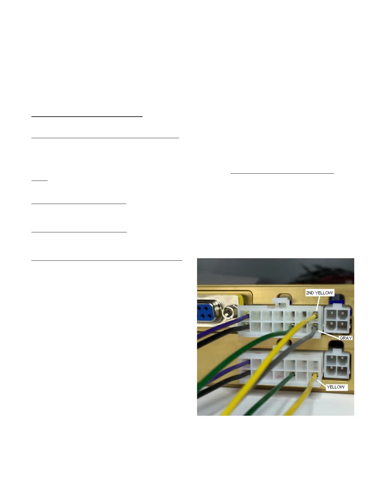
Dual board running two coilpacks, use this photo below:
Install yellow and gray wires as shown in the photo.
Insert the gray wire terminal into the lower right position of
the upper main harness connector.
Insert one of the yellow wires terminal into the lower right
position of the lower main harness connector. Insert the
other yellow wire into the upper right position of the upper
main harness connector. We need the two yellow wires
connected together due to system complexity.
Note, the upper is primary closest to enclosure lid, lower
is closest to the mounting flange.
Connect the Gray wire to L on the aircraft key switch, or to
your toggle kill switch labeled L.
Connect the Yellow to R on the aircraft key switch, or to
your toggle kill switch labeled R.
If using toggle switches the other terminal of the toggle
switch must be connected to ground.
It may be wise to mark the upper and lower main harness
plugs so they do not get swapped in position if they are ever unplugged in the future.
Installations without the aircraft type key/mag switch
If you don’t have a typical aircraft key/mag type switch, you can wire up yellow and gray to one or two normally open
momentary push switches or toggle switches to kill ignition which will then shut down the engine. Remember turning
off Mainbus power to the CPi2 just forces it over to backup battery power so your Mainbus or ecu power switch will
not shut off the engine. Read on though, there is a window in the programmer that can shut down the engine
 Loading...