34
6 Cylinder Dual ECU Only Mixture Knob Relay connections
If you have a Single Board ECU skip this section. Photo below Knob Relay Box
The single mixture knob affects either or both ECUs via a special
Knob Relay box as shown in the photos. Knob relay to DB25
harness connections were covered above in this manual. Most
connections are simple plug in, but a few need to be connected
during installation, Yellow, Blue and Brown wires which exit a 3
wire Mate-N-Lok plug connected to the Knob real box. Photo right
shows Knob Relay Box.
Blue and Brown wires and connect to gray Injector relay box.
Terminals are pre-crimped onto the ends of the blue and brown
wires, insert into the R connector that goes into the Injector relay
box Right side. See photo R.
Insert Brown upper right corner, blue beside. Terminal orientation, latch wings should be on sides and
crimp folds visible on top. Should click when inserted all the way, compare depth of terminal with other
adjacent terminals already installed.
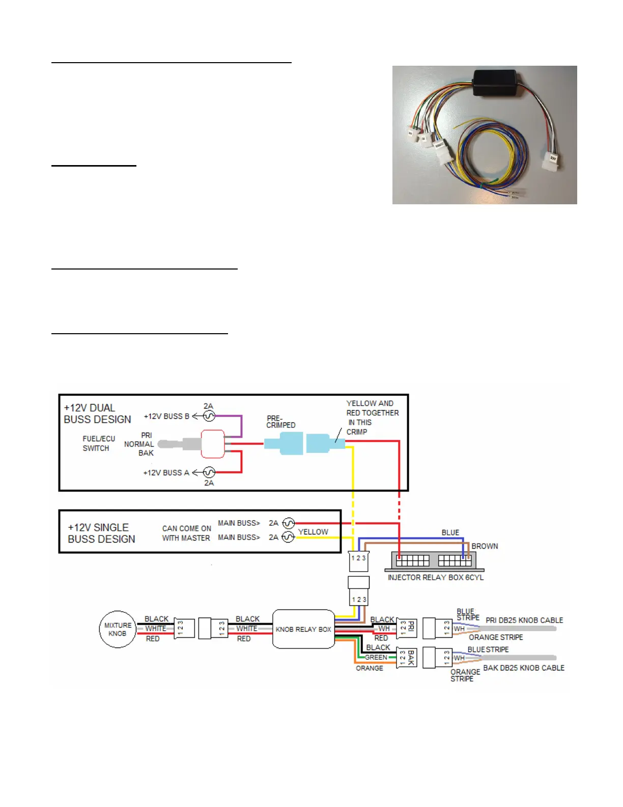
6 Cyl Dual ECU Single Power Buss:
Knob relaybox Yellow: Connect to main buss on 2A breaker, can turn on with master so no switch
needed. Repeat info: Injector Relay box red to 2A breaker, show again just for clarity. Skip over Dual
power buss section!
If 6cyl Dual with Dual Power Buss: Knob relaybox Yellow: Connect to the Injector Pri/Normal/Bak
switch. You will need to merge and crimp together this Yellow wire together with the Red wire from the
Injector Relay Box into a .250” spade terminal which connects to the Pri/Norm/Bak switch middle red
wire. See diagram below.
 Loading...