35
6 Cyl Dual ECU Dual Power Buss only connections
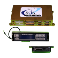
Photo right, closeup of Injector Relay Switch
Foreground 3 switch wires Purple To +12V Buss, 2A
breaker. Middle Red to Knob Relay and Injector
Relay +12V wires. Bottom red in photo to +12V Buss
A, 2A breaker.
Background prewired connections to Injector Relay
Box Left connector.
Prior to mid 2022 SPDT switches were used and after
that, DPDT switches were used in the event a
customer wanted to change to a DUAL +12V power
Buss design. If ordering a system it is best to indicate
if you plan to use a Dual Power buss. Note that a Dual Buss is when both busses are active all the time
and each power buss has its own battery and alternator. Systems will be prepared for Single Power Buss
unless you ask for Dual Power Buss setup. Only difference will be wires at the DPDT switch, 2
nd
set of
switch contacts will be unpopulated with red and purple wires. Wires could be added later if changing to
Dual Buss. If Single Power Buss, then the 2
nd
set of switch contacts aren’t used but could be wired to
annunciator lights or to an EFIS unit for switch position indication.
6 Cylinder Dual ECU Sensor information
Both ECU’s have their own Air Temp and CHT sensors. There is only one Throttle Position Sensor but
this is not a critical sensor so the signal is shared between each ECU. If you lose power on the Primary
ECU then the TPS will not function, but this will only result is slight hesitation if throttle is opened quickly.
The engine will run the same at steady throttle without a TPS signal.
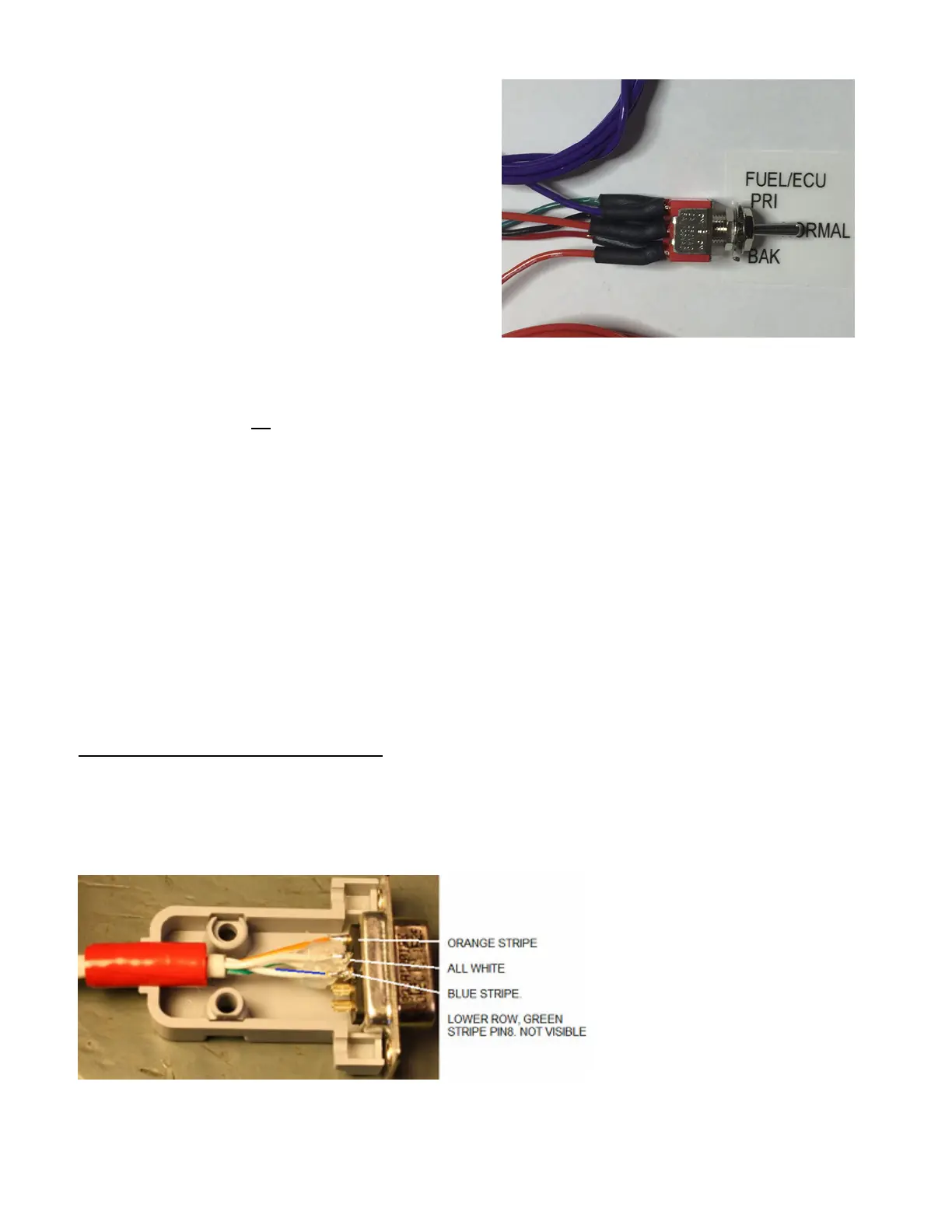
Hall sensor 9 pin D Sub
Plugs into the middle DB-9 port on the ECU. On Dual ECU systems, the primary harness and Hall sensor
cable is color coded green, plugs into the Primary(top)ECU and the backup ones are color coded red
plugs into the Backup(bottom) ECU
.
DB-9 Pin#, function, Tefzel cable colors:
5, +5V, orange stripe
4, Trigger, solid white
3, Ground, blue stripe
8, Sync signal, green stripe.
Wrap electrical tape around the cable several times to fill the gap where the cable exits the DB hood.
 Loading...