36
Programmer Cable(s)
These connect the ECU(s) to the programmer. Each ECU has a cable to plug
into the programmer. Pay attention to the labeling to be sure primary ECU is
plugged into primary programmer port and backup to backup.
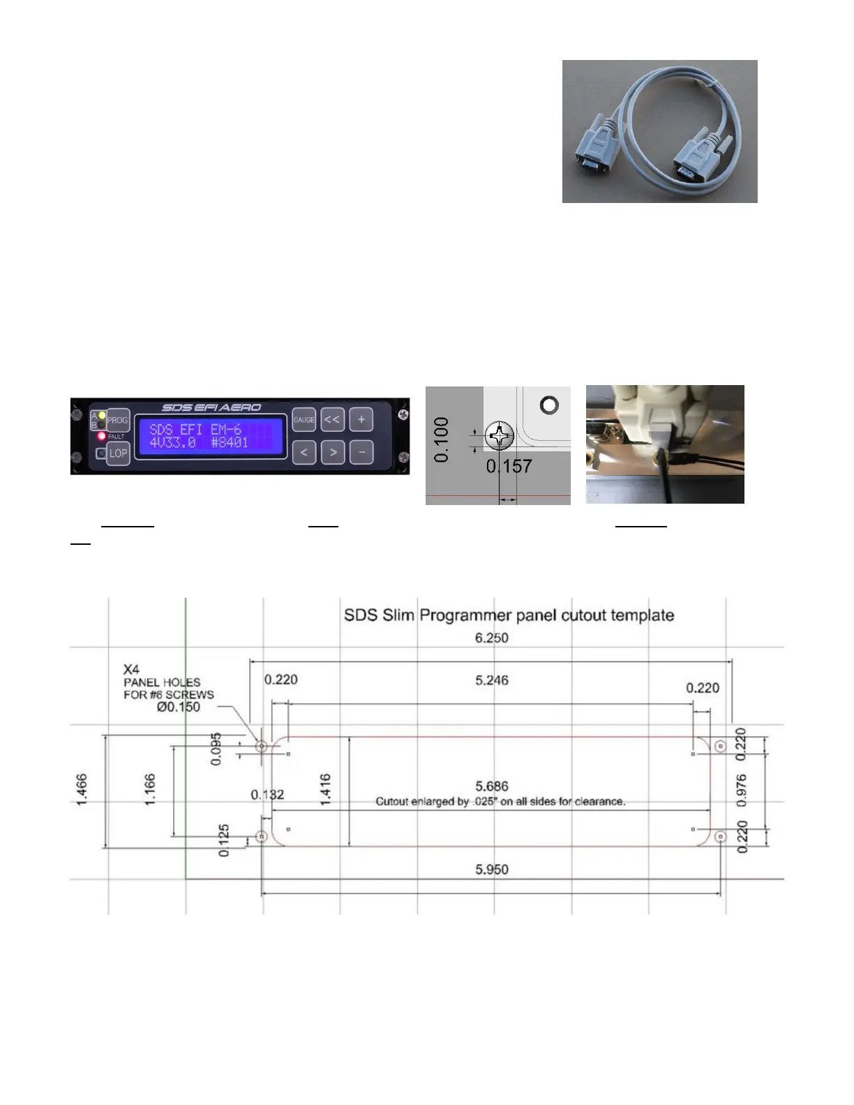
Panel Mount Programmers
For maximum flight safety, we recommend all aviation applications have a programmer
connected in the cockpit.
The Design1 EFI AERO programmer unit works with single or dual ecu’s. Designed to mount in the radio
stack (6.25 inches wide). Cutout opening is 5.636” wide by 1.366” high, with .195” corner radii. Cutout
dimension are zero gap so expand opening by desired amount to allow for powder coating. Mount holes
need to fit #6 screws. Mounting hole spacing is 5.95” x 1.166”. Use #6-32 x 3/8” long screws to mount.
Mounting hole dimensions from cutout opening are .157” to sides of cutout and .100” up from bottom of
cutout and .100” down from top of cutout.
The Primary ecu cable goes to the right side connector as viewed from the rear. Backup ecu goes to the
left connector. The 2ft black wires goes to chassis ground for static protection. L-brackets are to support
the cable weight. Be sure they contact the cable connector and adjust as needed. The L brackets have
slotted holes. Be careful swapped connectors can lead to confusion later!
Be aware that the diagram above has a larger cutout to allow for powder coating thickness, you may
wish to shrink the cutout for less clearance. Actual spigot dimensions are 5.672 X 1.366”.
 Loading...