GATE ARRANGEMENT
It is necessary to make controls on the gate to make sure the application of FLIPPER automation can be possible.
Make sure that:
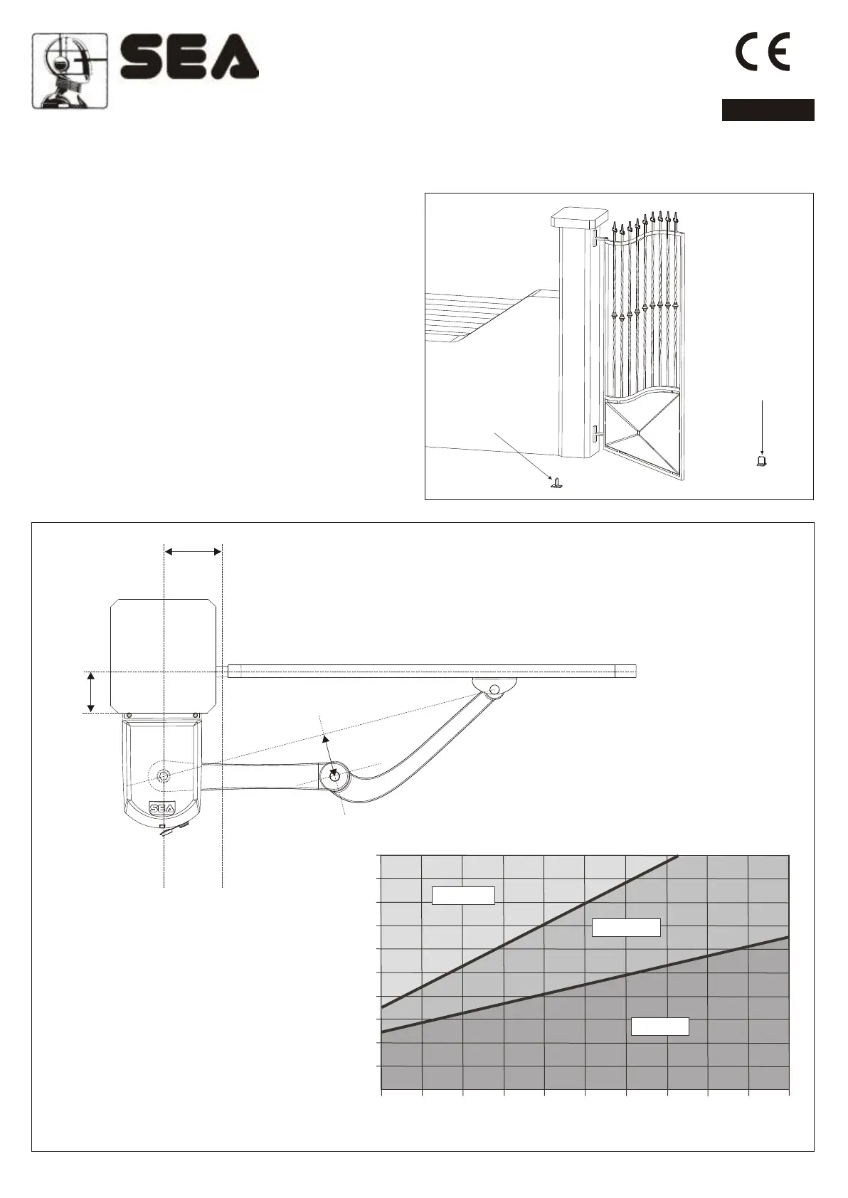
Fig. 7
A. The gate fixed and moving parts have a strong and crush-
proof structure;;
B. The weight of each leaf is not over 200 Kg (see drawing
pag. 18, Fig 4-A);
C. The length of each leaf is not over 2 m (see drawing pag.
18, Fig 4-A);
D. The hinges are strongly anchored and are able to support
the torque of the operator; they do not have irregular
movements and/or any friction during the whole movement of
the leaf;
The FLIPPER operator comes with limit switch stop in opening
and closing, nevertheless it is recommended to install
mechanical limit switch stops to be fixed on the ground in
FLIPPER
B
A
C 1 /12 mm 00 0
MAX 250 mm
19
Fig. 8
105°/110°105°/110°
100°/105°100°/105°
90°/100°90°/100°
300300
280280
260260
240240
220220
200200
180180
160160
140140
120120
100100
00 2525 5050 7575 100100 125125 150150 175175 200200 225225 250250
BB
AA
Limit Switch stop
in opening
Limit Switch stop
in closing
DIMENSIONS FOR THE INSTALLATION
FITTING AND CONNECTION INSTRUCTIONS
ENGLISH
Sistemi Elettronici
di Apertura Porte e Cancelli
International registered trademark n. 804888
®
REV 02 - 03/2009