EasyManua.ls Logo

SEA TAURUS - User Manual

SEA TAURUS
4 pages
Print Icon
To Next Page IconTo Next Page
Loading...
22
33
11
66
44
55
Opening
Electronic Systems
TAURUS
An electro-mechanical reduction operator within an aluminium
casing.
The TAURUS can be supplied with either:
A mechanic friction clutch or electronic sensing device as
methods of limiting the motor torque.
The gates open & close stop limits are accurately archivied by
mechanically triggering the on-board micro-switch.
Manual release is quickly archieved by operating a key operated
manual release system.
The microprocessor control unit has a choice of automatic or
semi-automatic control logic and will provide all normal safety
logic functions.
1 Adjusting screw mechanical clutch
2 Magnetic encoder
3 Limit switch
TECHNICAL DATA
Power supply
Power
Thrust force
Capacitor
Use rate
Absorbed current
Gate speed (pinion Z20)
Housing protection
115 V (±5%) 50/60 Hz
200 W
2 A
12 Nm
35uF
10,2 In/sec
30 %
IP 55
REV 00 - 10/2003
Gate arrangement
The first thing to check is that the gate is in good running order as
follows:
a) The gate is rigid and straight and runs smoothly throughout its travel.
b) that the inferior sliding guide-rail is perfectly straight and horizontal to
avoid a derailment of the gate (fig. 1); furthermore it must be free of
irregularities and foreign bodies which could obstruct the normal run of
the gate (fig. 2 and 3).
c) that the upper guides are not fixed (fig. 4) but furnished with rollers
which allow the sliding of the gate without difficulties (fig. 5 and 6).
d) that the distance between the end of the gate ( in maximum opening
position) and the eventual wall must be at least of 5 inches (fig. 7).
e) The lower support wheels have sealed bearings or grease points.
f) The top guide must be manufactured and installed so that the gate is
perfectly upright.
g) Physical gate stops must be fitted to prevent the gate coming out of
its guides and track.
Fig. 1 Fig. 2 Fig. 3
Fig. 4 Fig. 5 Fig. 6
1/2”
1/4”
5”
Fig. 7
!!
WARNING
Serious Injury Or
Death To
Pedestrians May
Result If This
Operator Is Used
In This Manner
- Persons are to keep clear! The gate can move without prior WARNING.
- Do not allow children to operate the gate or play in the gate area
- Persons are to operate the gate only when the gate area is sight and free of
people and obstructions
- This entrance is for vehicles only. Pedestrians must use separate entrance
!!
RN
W
A
I
G
N
niu
r
Se
o
I
jr O
s
u
y
r
e
t
T
D
a
h
o
P
e
t
a
s
M
d
r
ys
i
n
a
e
s
I
s
R l
Th
e
u
t
f
i
e
a I
Us
d
Op
rt
r
s
e
o
r
T
h
s
n
n
e
I
i a
n M
Pe-
n
l !
e
at
e
an
m
o
o
p
I
s
o e
t
e
epc
a
r
g c
t
h
t
ir W
A
R
N
G
.
s
ro
k e
h
v
e
w
r N
r a
T i
u
o
c
l
o
n e
o
l
o r e
r
h
g
l t
h
g
a
on
a
i
d
t pt
pa
y
i e
a
- D lw
he
n
ooa
e
e
a
t
e
r a
t
e
rt
t
a
a
a
g
s
a
ro o
e
e
e
ony
w
h e
i
e
f
- P
e
r
n
e
r t
h
g
a
t
e
r s
i
t
df
e
o
o e
t pt
t l
en
t
h
e
g a
s
h
n
r
s
a
t
p l
d
o c
i
s
p
t
u
n
eo
e
a
nb s
r o
n
s
e e
a
i t a s
f
r
v
es
o y
.
st
i
s
m
s
s e
en r
ce
h
n
r
e
o i e
r
a
n u
u
ar
-
T s
e
c
i
h l
n
l
P
ed
t p
a
n
e
c
t t
Fig. 8
Important: Install the warning signs
which informs the pedestrians about
the danger they run when passing or
resting in the environment of the gate.
4 Foundation plate
5 Electronic control unit
6 Release
FITTING AND CONNECTION INSTRUCTIONS
1”
3
11
Question and Answer IconNeed help?

Do you have a question about the SEA TAURUS and is the answer not in the manual?

Summary

Gate Arrangement and Initial Checks

Gate Operational Check

Ensure the gate is in good running order before installation and connection.

Installation and Release Procedures

Mounting Plate Installation

Instructions for correctly installing the mounting plate for the gate operator.

Release Device Operation

Procedures for releasing and reconnecting the gate operator manually.

Adjustment Procedures

Limit Switch Adjusting

Adjusting limit switches for precise gate opening and closing.

Clutch Adjustment

Adjusting the clutch for sensitivity and pushing force.

Safety and Warnings

Important Safety Instructions

Crucial safety information regarding operator use, risk of injury, and maintenance.

Risk Explanation

Explanation of potential risks associated with gate operation and installation.

Overview

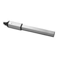
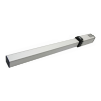
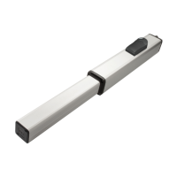
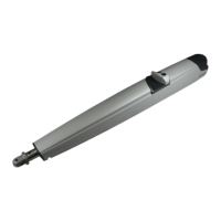
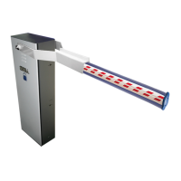
The device described in this manual is the SEA TAURUS, an electro-mechanical reduction operator designed for automating sliding gates. It is housed within an aluminum casing, ensuring durability and protection from the elements.

Function Description:

The TAURUS operator is designed to open and close sliding gates smoothly and efficiently. It incorporates a reduction mechanism to provide the necessary torque for gate movement. The device can be supplied with either a mechanical friction clutch or an electronic sensing device to limit the motor torque, enhancing safety and preventing damage to the gate or operator in case of an obstruction. Gate open and close stop limits are precisely achieved by mechanically triggering on-board micro-switches. For manual operation during power outages or emergencies, a key-operated manual release system is provided, allowing quick disengagement of the drive. The integrated microprocessor control unit offers a choice of automatic or semi-automatic control logic and supports all normal safety logic functions, ensuring safe and reliable operation.

Important Technical Specifications:

  • Power supply: 115 V (±5%) 50/60 Hz
  • Power: 200 W
  • Absorbed current: 2 A
  • Thrust force: 12 Nm
  • Capacitor: 35uF
  • Gate speed (pinion Z20): 10.2 In/sec
  • Use rate: 30%
  • Housing protection: IP 55

Usage Features:

Before installation, it is crucial to ensure the gate is in good running order. This includes checking that the gate is rigid and straight, runs smoothly, the inferior sliding guide-rail is perfectly straight and horizontal, free of irregularities, and that upper guides are not fixed but furnished with rollers allowing smooth sliding. A minimum distance of 5 inches between the end of the gate (in maximum opening position) and any eventual wall is required. Lower support wheels should have sealed bearings or grease points, and the top guide must ensure the gate is perfectly upright. Physical gate stops must be fitted to prevent the gate from coming out of its guides and track. Warning signs must be installed to inform pedestrians about potential dangers.

Mounting Plate Installation:

A mounting plate, manufactured to specific dimensions (as shown in Fig. 9), is required. This plate needs concrete holding ties welded to its base. It is recommended to raise the plate 2 inches from the finished level to prevent water accumulation around the operator. During concreting, necessary cable ducts (minimum 1" dia.) and cables should be installed through the base plate, ensuring sweep bends instead of elbow ones. The plate must be perfectly leveled. The chain must maintain a minimum distance of 3 inches from the gate.

Release Device:

To manually release the gate:

  1. Unscrew the releasing cap on the side of the operator opposite to the pinion (Fig. 11).
  2. Insert the hexagon "T" key (Fig. 11) and turn it clockwise without forcing until it stops (Fig. 12).
  3. Manually open and close the gate.

To reconnect the drive:

  1. Insert the hexagon "T" key (Fig. 11) and turn it anticlockwise without forcing until it stops (Fig. 12).
  2. Slowly manually slide the gate until it reconnects the drive.
  3. Do not attempt to use the operator electrically before reconnecting the drive.

Limit Switch Adjusting:

Before adjusting the limit switches, ensure the motor reducer (complete with chain) is assembled at the gate, the limit switch cursor is in the central position of its run, and the gate is in the middle of its opening. To install and adjust limit switches in opening:

  1. Release the motor reducer.
  2. Bring the gate to the complete opening.
  3. Act on the adjusting screw so the microswitch activates contact with the cursor (Fig. 13). To install and adjust limit switches in closing:
  4. Release the motor reducer.
  5. Bring the gate to the complete closing.
  6. Act on the adjusting screw so the microswitch activates contact with the cursor (Fig. 14). For more accurate adjustment, fine-tune the adjusting screws during the testing phase.

Clutch Adjustment:

To adjust the clutch:

  1. Turn the stop of the electronic control unit and unscrew the fixing nut, keeping locked screw "A" (Fig. 15).
  2. Use a hexagonal key to act on the "A" screw (Fig. 16).
    • Clockwise rotation: less clutch sensibility and more pushing force.
    • Anti-clockwise rotation: more clutch sensibility and less pushing force.

Maintenance Features:

The manual emphasizes the importance of regular maintenance and safety checks. The system opener should be tested monthly to ensure it reverses on contact with a 1-1/2 inch high object (or a 2x4 board laid flat) on the floor. Improper adjustment of force or travel limits increases the risk of severe injury or death. The gate system must be properly balanced and maintained, as improper balancing or maintenance can lead to severe injury or death. A qualified service person should perform repairs to cables, spring assemblies, and other hardware.

The installer is responsible for conducting a thorough risk examination to prevent crushing, conveying, cutting, grappling, trapping, and other hazards, ensuring a safe installation for people, things, and animals, in accordance with local laws. The owner/operator and/or installer should determine if the equipment and optional devices are suitable and safe for the intended use. Warranty is void if the unit is installed or wired improperly, used with the wrong power source or hydraulic fluid, or if damage is caused by fire, flood, lightning, or other acts of God.

Safety Instructions:

  • Never allow children to operate the gate or play in the gate area. Keep remote controls away from children.
  • Always keep the moving system in sight and away from people and objects until it is completely closed or stopped. No one should cross the path of the moving system.
  • Operate the gate only when fully visible, properly adjusted, and free of obstructions.
  • This entrance is for vehicles only; pedestrians must use a separate entrance.
  • The installer must instruct the user on the proper operation of the gate operator system and how to periodically test reversing devices (reversing loops, photo-eyes, reversing edges).
  • In case of emergency, the installer should instruct on how to remove the gate operator system from service, shut off power at the service panel, and manually operate the gate.
  • Packaging materials (plastic bags, foam polystyrene, nails, etc.) must be kept out of children's reach due to potential dangers.

SEA TAURUS Specifications

General IconGeneral
BrandSEA
ModelTAURUS
CategoryGate Opener
LanguageEnglish

Related product manuals