EasyManua.ls Logo

SEA COMPACT Series User Manual

Default Icon
20 pages
To Next Page IconTo Next Page
Page #1 background imageLoading...
Page #1 background image
COMPACT
SUPER COMPACT
INSTALLATION MANUALS
AND SAFETY INFORMATION
web site: www.sea-usa.com
e-mail: sales@sea-usa.com
REV 05 - 04/2018
67410796
International registered trademark n. 2.777.971
SEA USA Inc.
10850 N.W. 21st unit 160 DORAL MIAMI
Florida (FL) 33172
Phone:++1-305.594.1151 Fax: ++1-305.594.7325
Toll Free: 800.689.4716
Question and Answer IconNeed help?

Do you have a question about the SEA COMPACT Series and is the answer not in the manual?

SEA COMPACT Series Specifications

General IconGeneral
Motor voltage24V DC
Operating temperature-20°C to +55°C
Limit switch typeMagnetic
Power supply230V AC, 50Hz
Safety FeaturesObstacle detection

Summary

Key Safety Information

General Safety Precautions

Essential precautions for safe installation, use, and maintenance of the gate operator.

Critical Safety Instructions

Critical instructions to reduce the risk of injury or death during operation.

Periodical Maintenance Guide

Maintenance with Power Off

Maintenance tasks performed after turning off the power supply.

Power Off: Battery & Connection Checks

Verifying battery conditions and connection integrity when power is off.

Maintenance with Power On

Maintenance tasks performed after turning on the power supply.

General Safety and Installation Information

Core Installation Instructions

Non-Contact Sensor Placement

Guidelines for placing non-contact sensors for safety.

Contact Sensor Placement

Guidelines for placing contact sensors for safety.

Important Notices and Disclaimers

UL 325 Changes for Gate Operators

UL 325 Gate Operator Classes

Entrapment Protection Requirements

GATE WARNINGS AND PRECAUTIONS

Gate Condition Checks

Ensuring the gate is in good running order before installation.

Operational Safety Precautions

Warnings regarding pedestrian safety and gate path usage.

FEATURES AND SPECIFICATIONS

Main Parts Nomenclature

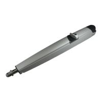
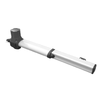
Identification and labeling of the primary components of the operator.

Unit Dimensions

Physical dimensions of the gate operator unit in inches.

Operator Capacity Graphic

Visual representation of operator capacities for width and weight.

Technical Specifications Overview

MECHANICAL INSTALLATION

Typical Installation Diagram

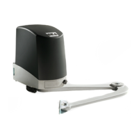
Illustrates the standard setup for gate operator installation.

Carrying Box Installation Guide

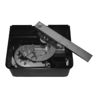
Instructions and dimensions for preparing the carrying box foundation.

Carrying Box Pit Preparation

Planning for water drainage and electrical cable passage in the pit.

Carrying Box Alignment

Ensuring the carrying box is horizontal and perpendicular to the gate axis.

Operator Unit Mounting

Steps for inserting and securing operator units into the carrying box.

Gate Leaf Assembly Procedure

Instructions for attaching the gate leaf to the operator.

Leaf Placement and Alignment

Ensuring correct leaf position and distance from the pillar.

Operator Installation Procedure

Motor Release System Operation

Release Mechanism Mounting

Adjustable Mechanical Stops

Pushing Force Regulation

Braking Regulation Guide

Compact/Super Compact Accessories

Leaf Release System Operation

Release Operation (Personalized Key)

Steps to release the gate leaf using a personalized key.

Release Operation (DIN Key)

Steps to release the gate leaf using a DIN key.

Risk Examination Requirements

Periodical Maintenance Schedule

Sales Conditions and Warranty Information

Related product manuals