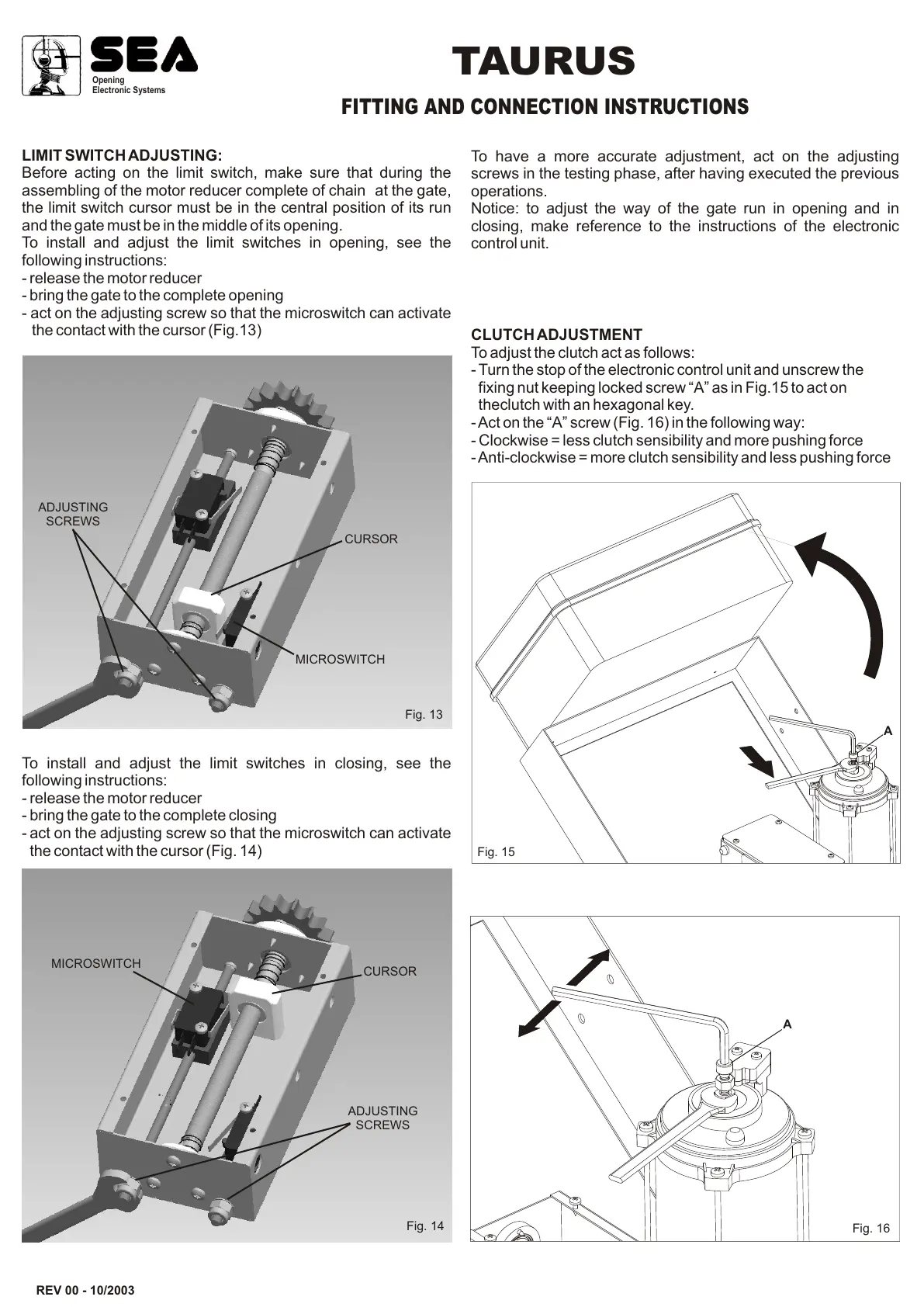
CLUTCH ADJUSTMENT
To adjust the clutch act as follows:
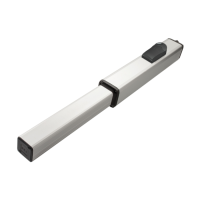
- Turn the stop of the electronic control unit and unscrew the
fixing nut keeping locked screw “A” as in Fig.15 to act on
theclutch with an hexagonal key.
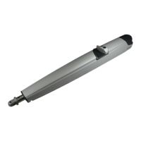
- Act on the “A” screw (Fig. 16) in the following way:
- Clockwise = less clutch sensibility and more pushing force
- Anti-clockwise = more clutch sensibility and less pushing force
REV 00 - 10/2003
Fig. 14
To have a more accurate adjustment, act on the adjusting
screws in the testing phase, after having executed the previous
operations.
Notice: to adjust the way of the gate run in opening and in
closing, make reference to the instructions of the electronic
control unit.
Fig. 16
MICROSWITCH
ADJUSTING
SCREWS
Opening
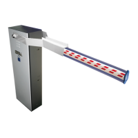
Electronic Systems
TAURUS
FITTING AND CONNECTION INSTRUCTIONS
A
LIMIT SWITCH ADJUSTING:
Before acting on the limit switch, make sure that during the
assembling of the motor reducer complete of chain at the gate,
the limit switch cursor must be in the central position of its run
and the gate must be in the middle of its opening.
To install and adjust the limit switches in opening, see the
following instructions:
- release the motor reducer
- bring the gate to the complete opening
- act on the adjusting screw so that the microswitch can activate
the contact with the cursor (Fig.13)
To install and adjust the limit switches in closing, see the
following instructions:
- release the motor reducer
- bring the gate to the complete closing
- act on the adjusting screw so that the microswitch can activate
the contact with the cursor (Fig. 14)
CURSOR
MICROSWITCH
ADJUSTING
SCREWS
Fig. 13
CURSOR
Fig. 15
A