
J
Julie MartinezAug 4, 2025
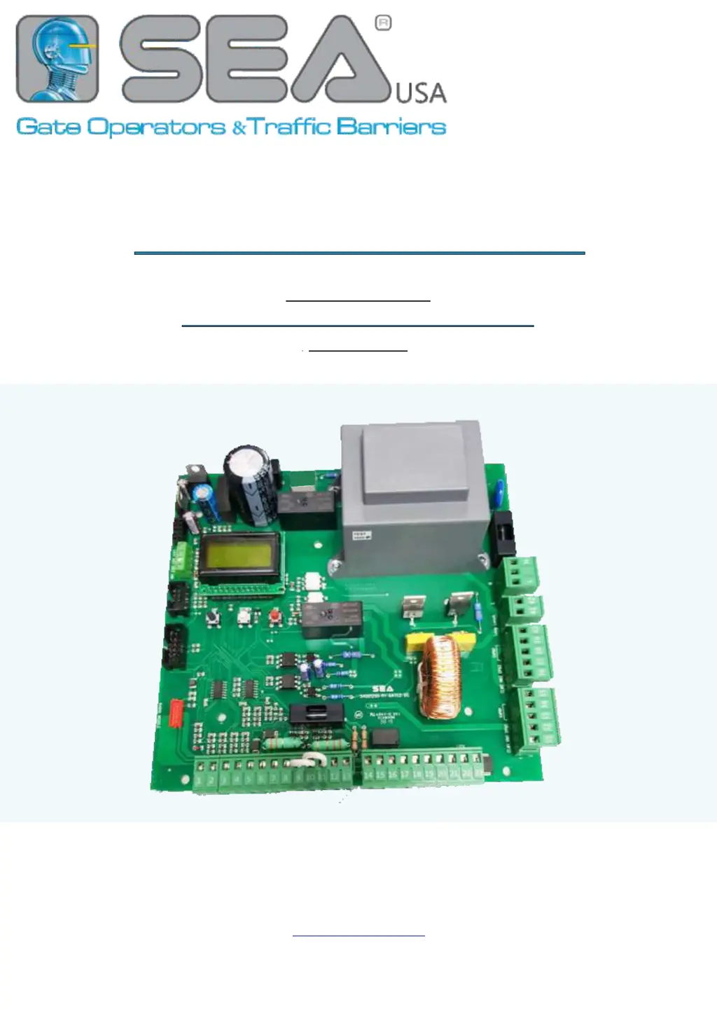
What to do if the SEA GATE 2 DG R1B gate opens but doesn’t close?
- RRyan ParkAug 4, 2025
If your SEA Control Unit gate opens but doesn’t close, it could be due to several reasons: * The contacts of the photocells are connected and open. * The stop contact is connected and open. * The edge contact is open. * Ammeter alarm. * Encoder alarm. Check the jumpers or the signals indicated on the warning lamp. If the ammeter alarm has intervened, increase the torque parameter. Also, check the reading of the Encoder and/or the sensibility.