Quantity
1
1
1
1
1
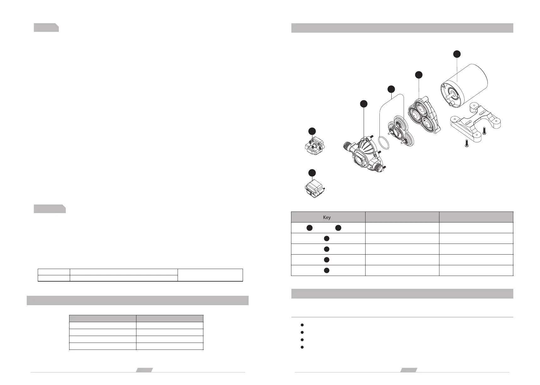
REPAIR KITS
ELECTRICAL INFORMATION
Ft. (M)
0-20 (0-6)
30-50 (9-15)
20-30 (6-9)
50-65 (15-19)
AWG (MM²)
16 AWG
14 AWG
12 AWG
10 AWG
Description
Pressure switch
Pump Head Assembly
Valve Assembly
Diaphragm Assembly
Motor Assembly
TROUBLESHOOTING
PULSATING FLOW– PUMP CYCLES ON AND OFF
Check fitting tightness for air leaks.
Check lines for kinks.
Plumbing lines or fittings may be too small.
Clean faucets and filters.
3
page
2
page
Notes
5. All 115 VAC and 230 VAC pump motors and systems, MUST be ground per local and state electrical codes.
1. Flexible potable water hose or PEX tubing is recommended instead of rigid piping at pump. If you choose to
use rigid piping, provide a short length of hose between pipe and the pump to avoid noise and vibration.
2. We do not recommend the use of metal fittings. When possible, use the provided plastic fittings.
3. Do not adjust the bypass personally without the help of technician.
4. Lack of sanitizing and maintenance is one of the main reasons of under performance of the pump. Please do
maintenance and winterize the pump at appropriate times, especially before and after a period of storage.
115 AC
230 AC
BLACK(common),WHITE(neutral),GREEN(ground)
BROWN(common),BLUE(neutral),GRN/YELL(ground)
#16 AWG C-UL-TEW / UL 1015
2
(or heavier) [Mm ]
B
C
D
E
9. Use clamps at both ends of hose to prevent air leaks into the water line.
12. This pump should be wired on its own dedicated circuit. Connect the positive lead (red) to the positive
terminal of your battery and the negative wire (black) to the negative terminal of your battery.
3. Intake hose must be minimum 1/2" (13 mm) ID reinforced hose. Main distribution line from pump outlet should
also be 1/2" (13 mm) ID with branch and individual supply lines to outlets no smaller than 3/8"(10 mm).
2. Secure the feet, but do not compress them. Overtightening the securing screws may reduce their ability to
dissipate noise and vibration.
4. Plumb the system using high pressure (2x pump rating), braided, flexible tubing to minimize vibration/ noise.
8. The fittings must be secured to avoid leakage.
14. The electrical circuit should be protected with an over-current protection device (fuse) in the positive lead.
This pump requires a 18 amp fuse.
16. As the water supply pump is non-essential, reference the wire chart under the electrical information. Be
sure to have the correct wire sizing for the length of wire you are using.
1. The pump may be mounted in any position. If mounted vertically, the pump head should be in the down
position to avoid leakage into the motor casing in the event of a malfunction.
7. Strainer should be attached to the inlet side.
10. If a check valve is installed in the plumbing, it must have a cracking pressure of no more than 2 psi.
11. If applying a sealer or plumbing tape, be careful to not overtighten, as they may be sucked into pump.
5. Do not apply inlet pressure in excess of 30 psi. In general, try to avoid any inlet pressure completely.6. Avoid
any kinks or fittings which could cause excessive restrictions.
13. In an easily accessible location, install a switch to control electricity to the pump. Turn the pump off when
not used for extended periods or when the tank is empty.
15. The pump circuit should not include any other electrical loads.
17. After installation, check the voltage at the pump motor. Voltage should be checked when pump is
operating. Full voltage must be available at the pump motor at all times.
Setup
B
C
D
E
A
or
-1
A
-2
-1
A
-2
A
or
 Loading...