INSTALLATION
MANUAL
Section 2: ELECTRICAL INSTALLATION
1. Determine location of Seakeeper 5” Touch Display:
a. The desired location of the 5” Touch Display must be determined with respect to th
e
ves
sel’s arrangement.
b. The 5” Touch Display should be located on or near the helm or another easily accessibl
e
l
ocation.
2. Route CAN communications cable:
a. The CAN Cable Assembly, CABLE 3, is a 10 m shielded cable that connects the ConnectBo
x
t
o the 5” Touch Display.
CABLE 3 m
ust be routed and installed in the vessel from the Seakeeper wire harness CAN
Tee to the Tee Adapter at the Seakeeper 5” touch display, included with P/N 90600.
3. I
nstall Seakeeper 5” Touch Display equipment:
a. Console space required: Approx. 5.24” W x 3.70 H” (133 x 94 mm)
b. Mounting Instructions, Surface Mount: see Envelope and Mounting Details, 5” To
uch
D
isplay (90438) for details.
4. CAN communications tee adapter and terminator mounting instructions:
a. Console space required, Rear: Approx. 4 W x 3 H inches (102 x 76 mm), rear
b. Mounting Instructions: Rear mount on vessel console panel, within 2 ft (0.6m) of Display.
c. Hardware required: One mounting screw for .197” (5 mm) diameter mounting hole on Tee
Adapter.
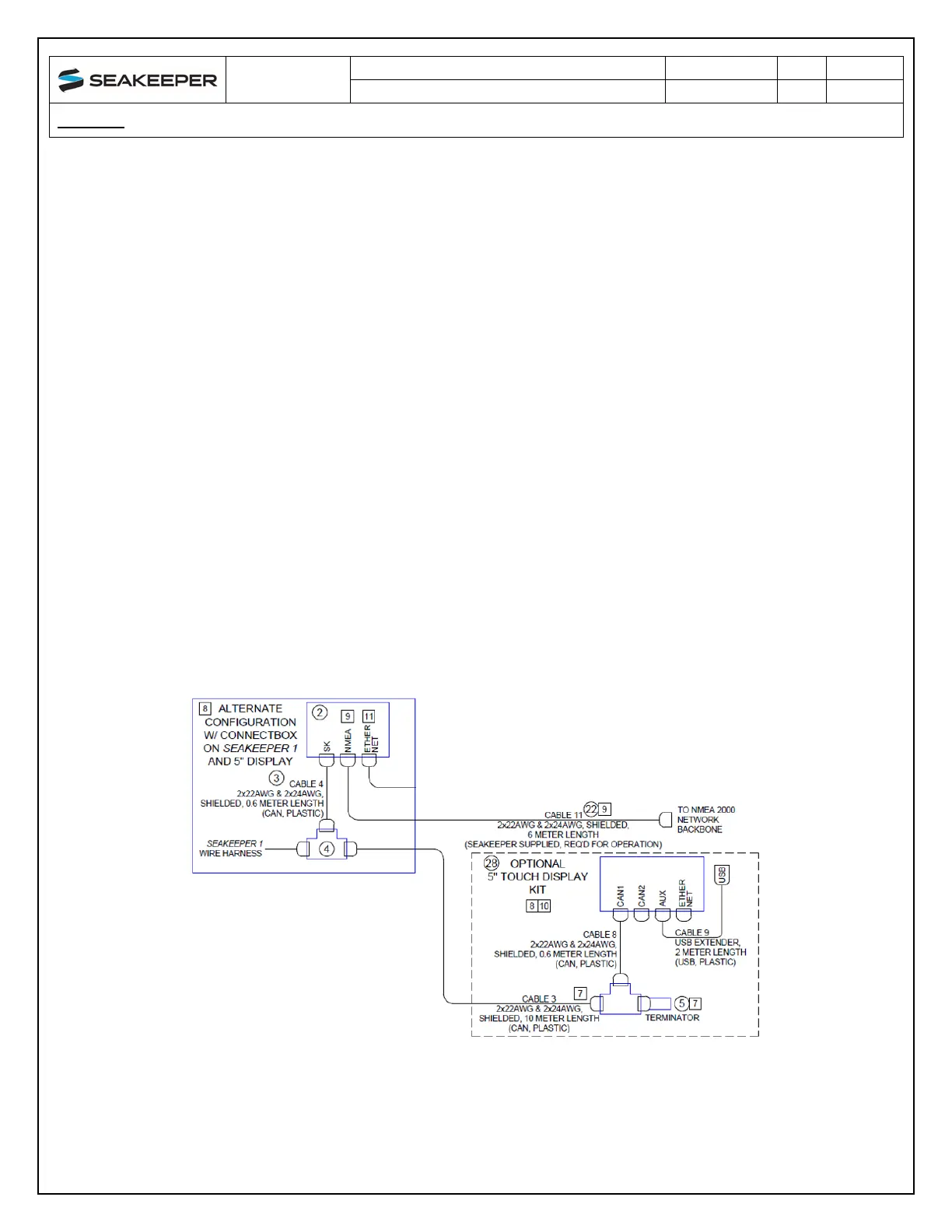
5. Connect Seakeeper 5” Touch Display Equipment:
a. The Seakeeper 5” Touch Display is connected in accordance with Drawing No. 90511, as
shown in the following Figure.
Figure 21: Seakeeper 5” Touch Display Connection (Drawing No. 90511)
 Loading...


