Section 1: SYSTEM OVERVIEW
1.3 Drive Box
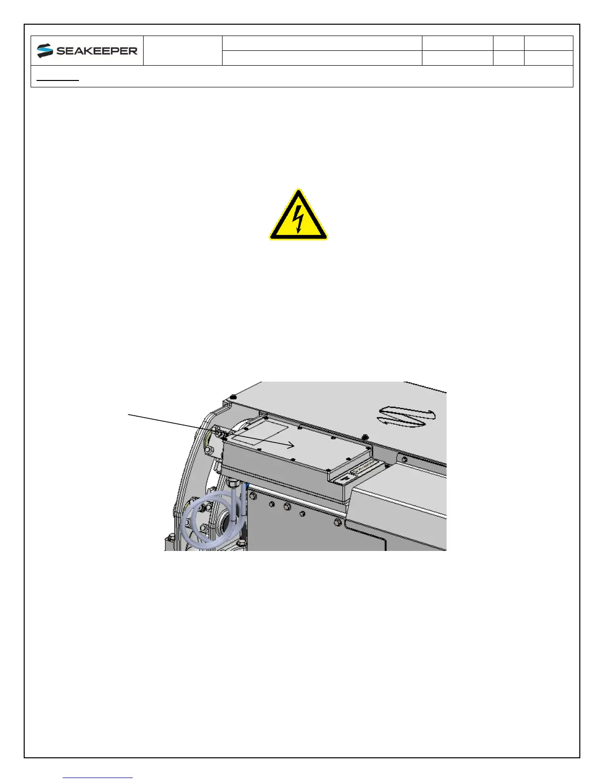
The glycol/water mix that cools the Seakeeper is also circulated through a cold plate inside the
Drive Box to remove heat from high-power electronic components.
The Motor Drive Box contains hazardous voltage and the
cover should not be removed while the flywheel is spinning
and the AC input voltage is present. This high voltage exists
even if the flywheel is coasting down and the supply voltage
has been shut off. The flywheel must be at Zero (0000) RPM
and AC input power disconnected for at least 10 minutes
prior to any service work on the motor drive box.
FIGURE 5 – DRIVE BOX
1.4 Electronic Control Module
The Electronic Control Module (ECM) monitors all the system sensors and automatically
regulates operation of the Seakeeper.
The controller commands the motor speed and regulates the Seakeeper’s precession rate and
gimbal angle. This is accomplished by commands to a high response flow control valve in the
hydraulic brake circuit that increases or decreases the brake pressure.