ECS400 | Issue 2 (H13F) 20/04/18
Original Language Version
© Jack Sealey Limited
3. SPECIFICATION
Output Voltage: ...........................................................12/24V
Output Charge Peak (EN) ....................................... 75A(50A)
Output Start Peak (EN) ....................................... 400A(300A)
Battery Range ...........................................................4-550Ah
Input Charge ............................................................... 1.5KW
Input Start .................................................................... 10KW
Charging Rates ........... 3xPreset+1XVariable to Current Max.
Supply .......................................................230V 1ph 50/60Hz
BSU ...................................................................... 30A-13.5V
Polarity Protection ...........................................Fuse (2x100A)
Fuse ..................................................................... ECS400.20
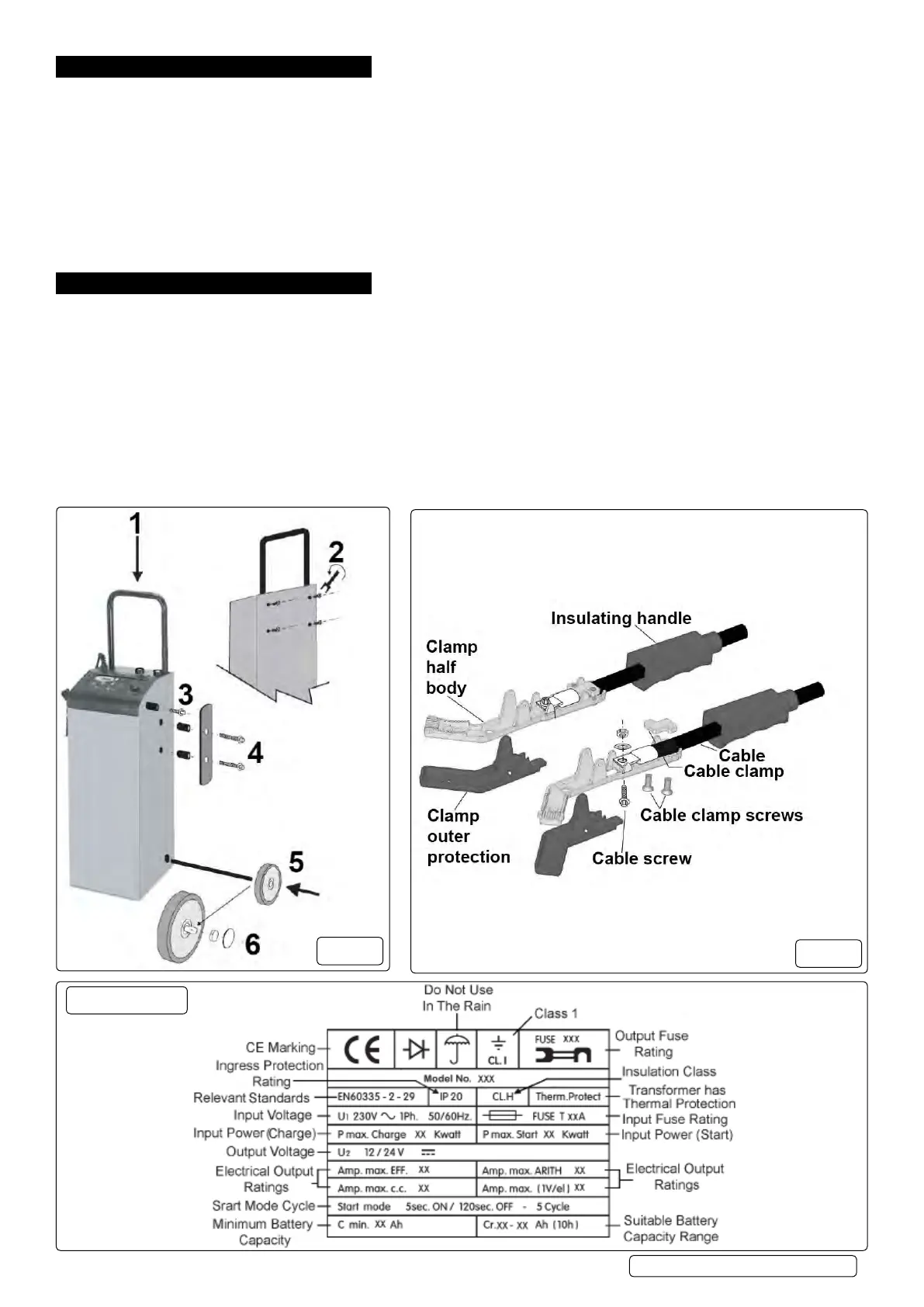
4. ASSEMBLY
4.1. Carefully unpack all components and prepare a surface on which you can lay the unit down on during assembly, without damaging it.
4.2. Insertthehandle(g.1.1)andsecureitthroughtherearoftheunitwithscrews(g.1.2).
4.3. Screwontheclampholderstoeachside(g.1.3).
4.4. Usethelongscrewstoscrewonthecableretainersandspacersoneachside(g.1.4).
4.5. Laytheunitonitsfrontinordertoinserttheaxle.Fitthewheels(g.1.5),thentheirretainersandcaps(g.1.6).
4.6. ClampAssembly(g.2).
4.6.1. Push cable through insulating handles.
4.6.2. Locate cable using cable screw washer and nut, note which way up cable needs to be. Screw on cable clamp tightly.
4.6.3. Screw up cable screw tightly.
4.6.4. Push outer protection pieces onto the ends of the clamp.
4.6.5. Slide insulating handles up to meet the outer protection pieces.
4.6.6. Repeat for all four clamps.
g.1
g.2
Data Plate