ECS400 | Issue 2 (H13F) 20/04/18
Original Language Version
© Jack Sealey Limited
5. CONTROL PANEL
5.1. Signalling LEDs.
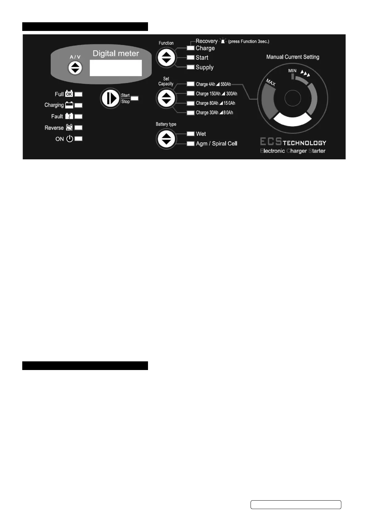
There are 15 LEDs on the front panel having the following functions:
•4batterystatusLEDs,indicating:
Full: ..............................battery is charged and is in Charge Maintenance status.
Charging: ..........................battery charging.
Fault: .............................battery is damaged.
Reverse:...........................polarity reversal.
•1batterychargerstatusLED: .........ON LED, battery charger ON (colour BLUE).
•1operatingstatusLED: ..............indicates whether output is in accordance with selected mode.
.................................Correlated with the Start/Stop button (Colour YELLOW).
•3LEDsonFunctionoperatingmode: ...Charge, Start or Supply (colour YELLOW)
•4batterycapacityindicationLEDs: ....Set Capacity described in section 6.2. (colour YELLOW).
•2batterytypeindicationLEDs:........Battery Type described in section 6.3. (colour YELLOW).
5.2. Operating mode selection buttons
There are 5 buttons on the front panel which have the following functions:
•Start/Stop: .......................starts or stops supply in the selected mode.
•Function: .........................selects operating mode.
•SetCapacity: ......................selects battery capacity.
•BatteryType: ......................selects the type of battery to charge.
•A/V: .............................selects the information to be displayed.
5.3. Digital Display.
5.3.1. A/V button:The A/V selector button selects voltage or current display or allows the user to change the display language.
Pressing theA/VbuttontogglesfromvoltagedisplayUtocurrentdisplayA,andnallytheLanguagemenu.Thismenuwillshowthe
message “LANGUAGE = ITALIAN” or another language, depending on the selection.
5.3.2. Change Display Language.
To enter the language selection mode, press the A/V button and hold it down when the display is showing the message
“LANGUAGE = ITALIAN”. The language setting is Italian by default; to scroll the language menu press the A/V button again and the
languageshownwillchangeinstantly.Languagessupported:•Italian•English.
Once the language is set, to quit the menu press the A/V button for a few seconds.
6. OPERATING MODES
6.1. Function.
Note: All modes support both 12V and 24V batteries (voltages stated for 12V batteries).
6.1.1. Charge Mode.
Battery charging mode. Provides 11 charging steps as described below:
•STEP1:Analysis1:Ifthebatteryoutputislessthan10.5Vtheunitproceedswiththenextanalysis.Outputsbelow5Vwillcausethe
charger to revert to stand-by.
•STEP2:Analysis2(sulphatedbattery):Thedisplayshowsthemessage“ANALYSIS”alternatingwiththeinstantaneousvoltage
or current. After this step the unit either starts the charging cycle directly or it displays the message “SULPHATED
BATTERY” to inform the operator that the battery must be recovered.
•STEP3:Desulphation:Pulsedvoltagetopreventsulphationofthebattery.
•STEP4:Controlledcurrent:Chargesthebatteryuptotheprogrammedlimitvalue.
•STEP5:Analysis3(elementsshortcircuited):Checkswhetherthebatteryhasshortcircuitedelementsorisdamagedand
reports the error, if present.
•STEP6:DeepCycleCharging:Centralchargingcycle.
•STEP7:ConstantVoltage:Keepsthebatteryatthechargingendvoltage.
•STEP8:Analysis4:.Checkswhetherthebatteryhasshortcircuitedelementsorisdamagedandreportstheerror,ifpresent.
•STEP9:Tricklecharging:Maintainsthebatteryat13.8V(WET)or13.5V(AGM/SPIRALCELL).
•STEP10:Analysis5:Checkswhetherthebatteryhasshortcircuitedelementsorisdamagedandreportstheerror,ifpresent.
•STEP11:Pulsedcurrentcycle:Cyclethatsimulatesthenormallifecycleofthebattery.
 Loading...