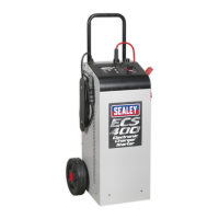
ECS400 | Issue 2 (H13F) 20/04/18
Original Language Version
© Jack Sealey Limited
6.1.2. Start Mode.
Tostartavehiclewithaatbattery,thismodeconsistsofthefollowingsteps:
•STEP1:Batteryanalysis:Thecharger’sStartLEDashes.
•STEP2:FastCharging:ThechargerentersthisstepiftheStartLEDissteadilyon.Itsetsthechargeendvoltageassociatedwiththe
selectedbatterytypewiththecurrentlimitdenedfortheStartstep.
•STEP3:EngineBoost:Whenthebatterychargerdetectsanenginecrankingattempt,itswitchestothenextstep.Ifthebattery
voltage reading is above 13.5V the scrolling message START appears on the display.
•STEP4:Boost:ThescrollingmessageSTARTappearsonthedisplay:thebatterychargerisnowdeliveringthemaximumpower.
6.1.3. Supply Mode.
Power supply mode to assist in vehicle programming. This mode does not contain any charging steps, and it consists exclusively of a
stabilised power supply delivering the nominal battery voltage. The purpose is that of supplying current to support the battery to prevent
it from being drained during operations that require power for short or long periods.
6.1.4. Recovery Mode.
WARNING: because of the high voltage reached during this cycle, the battery recovery process MUST be performed with the battery
disconnected and removed from the vehicle. Recovery with the battery connected to the vehicle may result in damage to the
vehicle’s electronics.
This is the method of recovery for sulphated batteries accessible by means of a prolonged press of 3 seconds of the Function button.
The screen displays the message RECOVERY alternating with the instantaneous voltage or current reading; during this step the
ChargeLEDashes.
The charger performs a special charging cycle in which higher than average voltages are forced to attempt recovery of the battery. In
this mode no error messages are generated during the charging cycle.
At the end of the cycle a message is displayed to indicate whether or not the battery has been recovered on the basis of the current
absorption.
This mode has six steps as described below:
•STEP1:Analysis1:Outputsbelow1.5Vwillcausethedevicetoreverttostandby.
•STEP2:Desulphation:Pulsedvoltageinordertopreventsulphationofthebattery.
•STEP3:ControlledCurrent:Chargesthebatteryuptotheprogrammedlimitvalue.
•STEP4:DeepCycleCharging:CentralChargingCycle.
•STEP5:HighVoltage:Keepsthebatteryathighvoltagefor2hourstoattempttobreakdownthesulphatecrystalsthathave
formed in the battery.
•STEP6:Analysis2:Checkswhetherornotthebatteryhasbeenrecovered.
6.2. Charging Mode:
6.2.1. Set Capacity.
Preset charging bands to select the connected battery, or for expert users, manual setting of the output current as a percentage of the
maximum current supported by the operating mode currently selected on the battery charger Manual Current Setting.
Specically:
•Charge: settablechargingband.
•Start: settablechargingband.
•Supply: Settablesupplyband,byManualCurrentSetting.
Charge 4Ah - 550Ah (Manual).
Supports all batteries from a minimum of 4Ah up to a maximum of 550Ah.
. Output current is adjustable from 0 up to the maximum supported by the operating mode currently selected on the battery charger.
Charge 150Ah - 300Ah.
. Supports batteries from 150Ah up to 300Ah. Output current adjusted automatically.
Charge 80Ah - 150Ah.
Supports batteries from 80Ah up to 150Ah. Output current adjusted automatically.
Charge 30Ah - 80Ah.
Supports batteries from 30Ah - 80Ah. Output current adjusted automatically.
6.3. Battery Type.
Wet: Acid electrolyte batteries.
Agm-SpiralCell:AGMbatterieswithatplateorOptimatypespiralcell.
6.4. Saving settings.
The battery charger saves the settings made on the control panel. In the event of an accidental power loss or voluntary power off,
when the charger is restarted, it will restart with the latest saved settings, including the Start/Stop status
6.5. Battery Analysis.
The analysis stages within the operating modes may terminate with the signalling of various errors:
•DamagedBattery:theFaultLEDswitchesonandtheStart/StopLEDswitchesoffandthechargerentersStandbymode.
The display shows the message Errxx where xx is the number corresponding to the cause of the error (see table). Single 10 second
audible warning.
•Polarityreversal:theReverseLEDswitchesonandthedisplayshowsthemessageErr07withatwosecondaudiblewarning.
•Analysisstepin:Charge:thedisplayshowsthescrollingmessageANALYSISalternatingwiththemeasuredvoltageorcurrent
value;theLEDcorrespondingtothefunctioncontinuestoashuntiltheanalysisisconcluded.Ifthebatteryisingoodcondition,the
LED will be on, otherwise the display shows scrolling message SULPHATED BATTERY and an intermittent audible warning is emitted.
•Analysisstepin:Start:inthepreliminaryanalysisfunctioninStart,theLEDofthismodewillashuntilacurrentabsorption
exceeding a minimum threshold is detected, after which the LED remains on and the vehicle engine can be started.
 Loading...