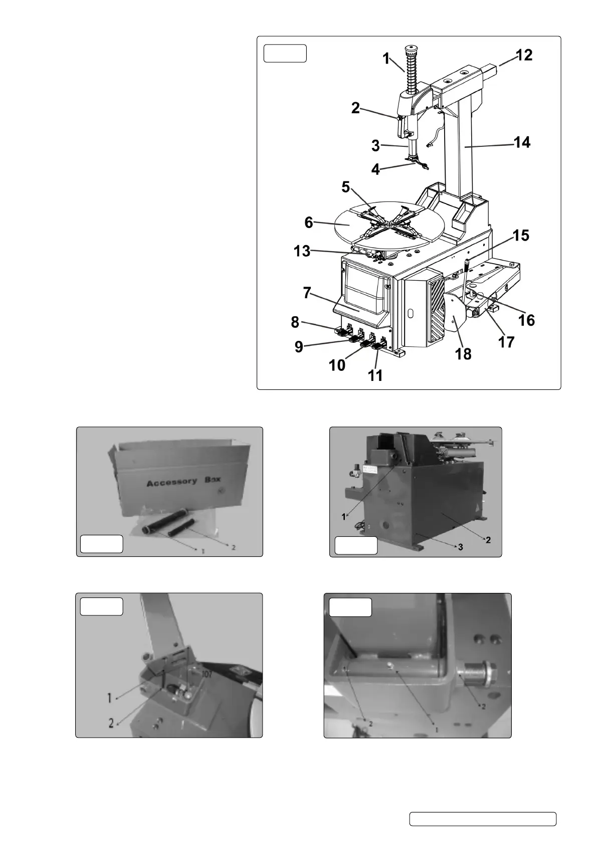
1. Vertical shaft spring
2. Handle valve
3. Hexagon shaft
4. Mounting/demounting head
5. Jaw
6. Turntable
7. Pedal label.
8. Column tilt pedal
9. Clamp pedal
10. Tyre bead braking pedal
11. Turn table pedal
12. Horizontal arm
13. Clamp turntable cylinder
14. Column
15. Blade handle
16. Bead breaking cylinder
17. Bead breaking arm
18. Bead breaking blade
5.3. Column Installation.
5.3.1. According to the requirements shown in g.1, position the main body of the machine. Unpack the accessory box and take out the
rotation shaft assembly g.3.1, and push out shaft assembly g.3.2. Clean the assembly and lubricate with oil.
5.3.2. Remove the xing screw g.4.1, remove the side panel g.4.2.
5.3.3. Remove the xing screw g.4.3, remove the tool box.
5.3.4. Lift up the column (two man lift) and insert the PU hose g.5.1. at the bottom into the hole g 5.2. on the top of the body. Adjust the
position of the column to make the rotation shaft bushing g.6.1 align with bearings g.6.2. Remove the nut and washer at the one
end of the rotational shaft assembly g.3.1. Push the shaft through the bushes and t the washer and tighten nut to a torque of
70Nm.
g.2
g.3
g.4
g.5
g.6
TC10 | Issue 1 02/02/18
Original Language Version
© Jack Sealey Limited