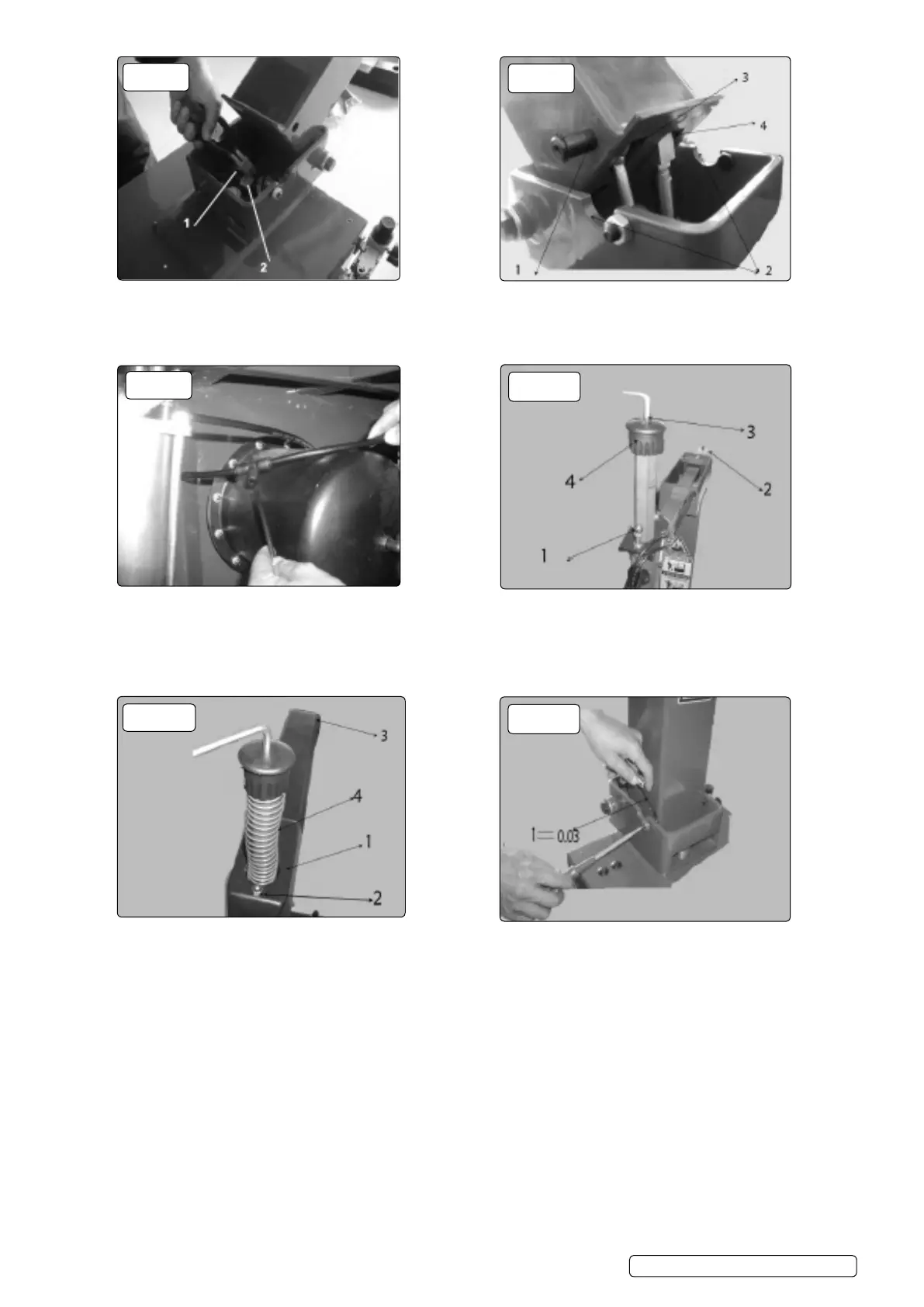
5.3.5. Tilt back the column and cut off the tie on the xed shaft g.7.1 and pull out the piston rod.
5.3.6. Position the column as shown in g.8. Remove the circlip from one end of the shaft g.3.2 and pass the shaft through the 16mm hole,
vertical retaining bar g.8.3, piston rod g.8.4 and through the hole on the opposite side of the column. Attach circlip to shaft.
5.3.7. To install the horizontal arm protective cover, remove the cap nut g.10.1, the screw at the back end g.10.2 and the screw g10.3 at
the top end of the vertical cap g.10.4. Remove cap g.10.4.
WARNING! when detaching the vertical shaft cap , support the vertical shaft to prevent the vertical shaft from falling.
5.3.8. Remove packaging from protective cover. Position as shown in g.11.
5.3.9. Twist on the cap nut g.11.2 and screw g.11.3. Install the vertical shaft spring g11.4, cap g.10.4 and screw g.10.3.
5.3.10. Adjust the column positioning screws on the two sides of the column. Release the nuts on the two sides and adjust the gap between
the head of the screw and the side of the column to 0.03mm g.12. and then lock the nut.
5.3.11. Connect the air source, use the lock air valve push button to lock the horizontal arm g.2.2. Operate the column tilt pedal g.2.8 and the
column will tilt backwards by about 25° . The speed of the movement of the column has been set to be about 2 seconds per stroke. After
a time in operation, the speed may increase or decrease, you can use the speed adjusting valve to adjust the speed. To do this
loosen the nut and turn the screw, turn the screw clockwise to decrease and counter-clockwise to increase. After adjustment, tighten the
nut.
5.3.12. Fix the side panel and tool box removed in step 4.2.2.
5.4. Compressed Air Installation
5.4.1. The compressed air regulator assembly can be found in the accessory box.
5.4.2. Use the screw provided to x the assembly on the right hand side (viewed from the back) of the body g.13.
g.7
g.9
g.11
g.8
g.10
g.12
TC10 | Issue 1 02/02/18
Original Language Version
© Jack Sealey Limited
 Loading...