JUMPER
WIRE
attacln to RH and W J TRANSFORMER
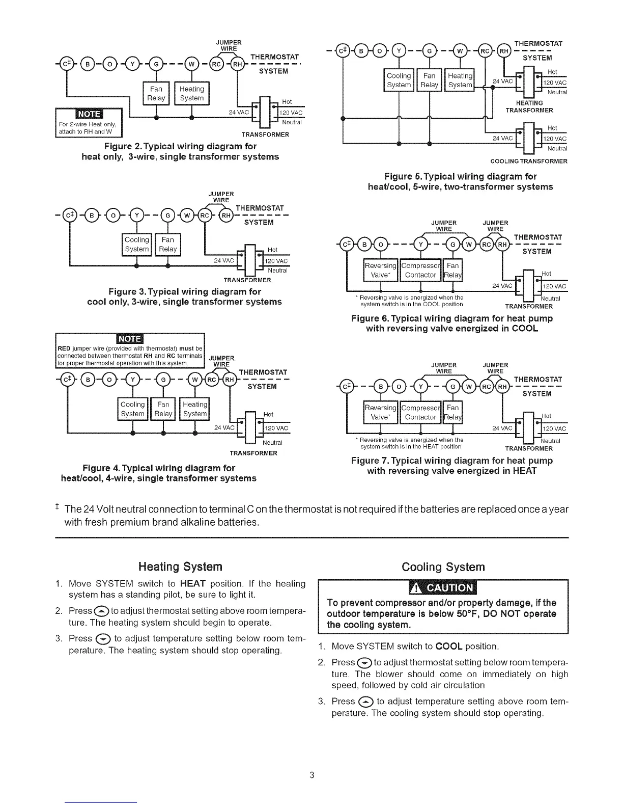
Figure 2.Typical wiring diagram for
heat only, 3-wire, single transformer systems
JUMPER
WiRE
TRANSFORMER
Figure 3. Typical wiring diagram for
cool only, 3-wire, single transformer systems
RED jumper wire (provided with thermostat) must be
_connected between thermostat RR and RC terminals_ JUMPER
_for proper thermostat operation with this system. _ WIRE
T o
TRANSFORMER
Figure 4. Typical wiring diagram for
heat/cool, 4=wire, single transformer systems
v
_)24_SYSTE:°t
l _ Neutral
a TRANSFORMER
24vAcLI 14.120wc
'==L_ Neutral
COOLING TRANSFORMER
Figure &Typical wiring diagram for
heat/cool, 5-wire, two-transformer systems
JUMPER JUMPER
WIRE WIRE
I _1 Contactor |U L____
_ ! ! L 24VAC U _C
* Reversing valve is energized when tlne _=J_Neutral
system switch is in the COOL position TRANSFORMER
Figure 6. Typical wiring diagram for heat pump
with reversing valve energized in COOL
* Reversing valve is energized when the
system switch is in the HEAT position
JUMPER JUMPER
WIRE WIRE
T
)mpressorll t-an I I
;°ntact°r ! Re[_
1 24wc
TRANSFORMER
Figure 7.Typical wiring diagram for heat pump
with reversing valve energized in HEAT
* The 24 Volt neutral connection to terminal C on the thermostat is not required ifthe batteries are replaced once a year
with fresh premium brand alkaline batteries.
Heating System
1. Move SYSTEM switch to HEAT position. If the heating
system has a standing pilot, be sure to light it.
2. Press (_ to adjust thermostat setting above room tempera-
ture. The heating system should begin to operate.
3. Press (_ to adjust temperature setting below room tem-
perature. The heating system should stop operating.
Cooling System
To prevent compressor and/or property damage, if the
outdoor temperature is below 50°F, DO NOT operate
the cooling system.
1. Move SYSTEM switch to COOL position.
2. Press (_) to adjust thermostat setting below room tempera-
ture. The blower should come on immediately on high
speed, followed by cold air circulation
3. Press (_ to adjust temperature setting above room tem-
perature. The cooling system should stop operating.
 Loading...