4
30" GAS RANGE INSTALLATION INSTRUCTIONS
2
Provide an adequate Gas Supply
When shipped from the factory, this unit is designed
to operate on 4" (10,16cm) water column (1.0 kPa)
Natural gas manifold pressure. A convertible pressure
regulator is connected to the range manifold and
MUST be connected in series with the gas supply line.
If LP/Propane conversion kit has been used, follow
instructions provided with the kit for converting the
pressure regulator to LP/Propane use.
Care must be taken during installation of range not to
obstruct the ow of combustion and ventilation air.
For proper operation, the maximum inlet pressure to
the regulator should be no more than 14" (35,56cm) of
water column pressure (3.5 kPa). The inlet pressure to
the regulator must be at least 1" (.25 kPa) greater than
the regulator manifold pressure setting. Examples: If
regulator is set for natural gas 4" (10,16cm) manifold
pressure, inlet pressure must be at least 5" (12.60cm); if
regulator has been converted for LP/Propane gas 10"
(25,4cm) manifold pressure, inlet pressure must be at
least 11" (27,9cm).
3
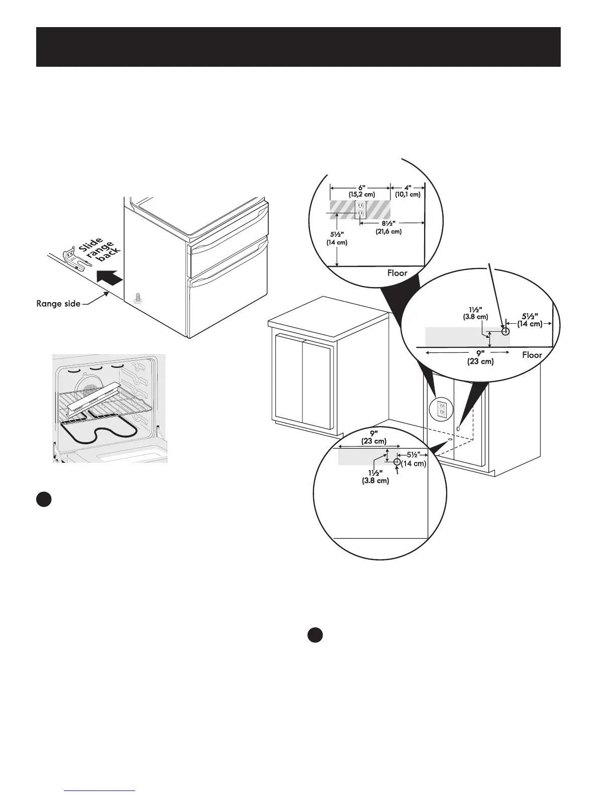
Seal the openings
Seal any openings in the oor under the range after
gas supply line is installed.
Recommended hole
location for through
the oor gas entry
line.
NOTE:
The gas entry line hole can be also placed
anywhere in the shaded area.
NOTE:
The electric outlet can
be placed anywhere
in the hatched area.
Recommended hole
location for through the
wall gas entry line.
Figure 5a
C. Level and position the range -
Slide range to its nal
position. Insert the range leveling leg in the anti-tip bracket.
Visually verify if the anti-tip bracket is engaged. Lower the
range by adjusting the 4 leveling legs alternatively until
the range is level. Check if the range is level by placing a
spirit level on the oven rack. Take 2 readings with the spirit
level placed diagonally; take a reading in one direction and
then in the other direction. Level the range if necessary by
adjusting the leveling legs.
Figure 3
Figure 4
Leak testing of the appliance shall be conducted
according to the instructions in step 4H.
The gas supply line should be ½" or ¾" I.D.