switch, when the V-D.-A slide switch is in the V-D.-A position.
The range is one-half that indicated by the pointer knob on the
RANGE switch, when the V-D.-A slide switch is in the V-A/2
position.
Select the required DC current range or use the procedure in
#2 above under OPERATING SUGGESTIONS. Connect the
test leads in series with the circuit to be measured. Observe
polarity. Read DC current on the appropriate scale. Be sure to
take the setting of the V-D. A slide switch into account, as
described in the DC VOLTAGE MEASUREMENTS section.
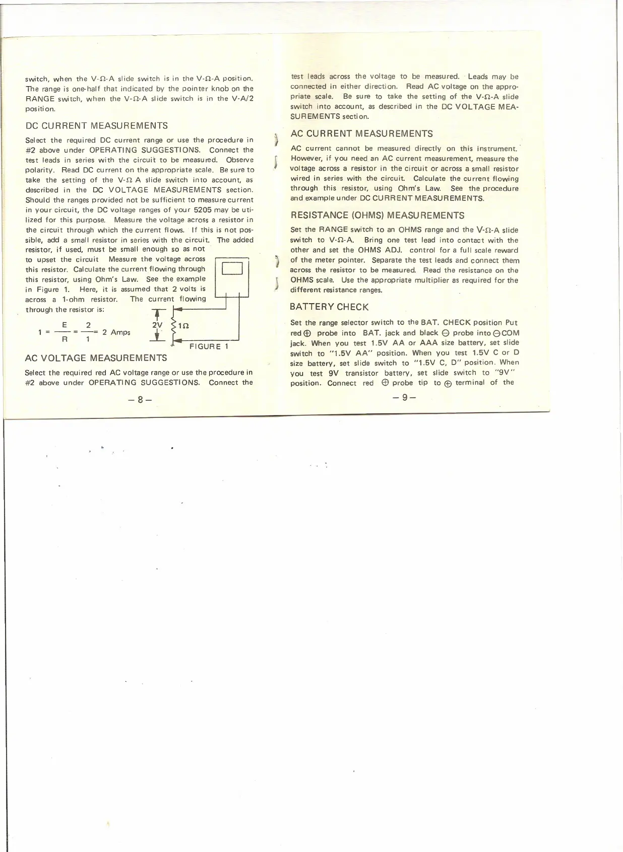
Should the ranges provided not be sufficient to measure current
in your circuit, the DC voltage ranges of your 5205 may be uti-
lized for this purpose. Measure the voltage across a resistor in
the circuit through which the current flows. If this is not pos-
sible, add a small resistor in series with the circuit. The added
resistor, if used, must be small enough so as not
to upset the circuit Measure the volt
this resistor. Calculate the current flowin
this resistor, using Ohm's Law. See th
in Figure 1. Here, it is assumed that
across a 1-ohm resistor. The curren
through the resistor is:
DC CURRENT MEASUREMENTS
E 2
1
=-- =-=
2 Amps
R 1
AC VOLTAGE MEASUREMENTS
T
2V
--.L
age across
D
g through
e example
2 volts is
t flowing
I
1D.
.
FIGURE 1
Select the required red AC voltage range or use the procedure in
#2 above under OPERA TI NG SUGGESTIONS. Connect the
-8-
-9-
test leads across the voltage to be measured .. Leads may be
connected in either direction. Read AC voltage on the appro-
priate scale. Be sure to take the setting of the V-D.-A slide
switch into account, as described in the DC VOLTAGE MEA-
SUREMENTS section.
)
j
AC CURRENT MEASUREMENTS
AC current cannot be measured directly on this instrument.'
However, if you need an AC current measurement, measure the
voltage across a resistor in the circuit or across a small resistor
wired in series with the circuit. Calculate the cu rrent flowing
through this resistor, using Ohm's Law. See the procedure
and example under DC CURRENT MEASUREMENTS.
RESISTANCE (OHMS) MEASUREMENTS
J
j
Set the RANGE switch to an OHMS range and the V-D.-A slide
switch to V-D.-A. Bring one test lead into contact with the
other and set the OHMS ADJ. control for a full scale reward
of the meter pointer. Separate the test leads and connect them
across the resistor to be measured. Read the resistance on the
OHMS scale. Use the appropriate multiplier as required for the
different resistance ranges.
BATTERY CHECK
Set the range selector switch to the BAT. CHECK position Put
red
(f)
probe into BAT. jack and black
e
probe into
e
COM
jack. When you test 1.5V AA or AAA size battery, set slide
switch to "1.5V AA" position. When you test 1.5V C or D
size battery, set slide switch to "1.5V C, D" position. When
vou
test 9V transistor battery, set slide switch to "9V"
position. Connect red
@
probe tip to
®
terminal of the
 Loading...