battery and black
e
probe tip to
e
terminal of the battery
to be tested. Read position of the meter scale. If the reading is
in the red "BAD" zone, the battery should be replaced. If
the green "GOOD" zone the battery has considerable life.
lf reading is white
"?"
zone you should consider making a
replacement, since very little power is left.
CAUTION: Always be sure that you identify the battery
polarity correctly before testing the battery.
DECEIBEL RATIO MEASUREMENTS
The ratio of two AC voltages can be expressed in terms of
dB. A standard has been adopted wh ich establ ishes one refer-
ence voltage as the 0 dB level. It is 0.774 volt rms (root mean
square). This assumes that 1 milliwatt is. developed across an
impedance of 600 ohms.
When using the 10 ACV range, read the dB scale if the V-n-A
slide switch is set to V-A/2. For dB measurements on the other
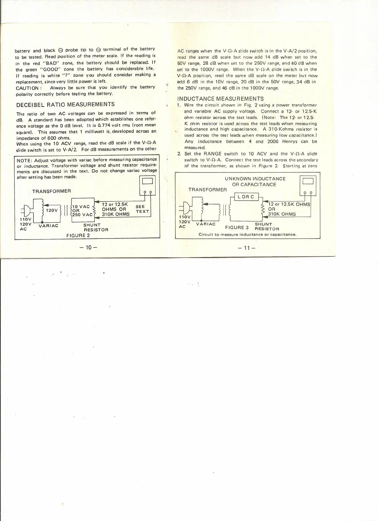
NOTE: Adjust voltage with variac before measuring capacitance
or inductance. Transformer voltage and shunt resistor require-
ments are discussed in the text. Do not change variac voltage
after setting has been made.
.---
0
TRANSFORMER
l+r-
mil
10 VAC
120r12.5K
SEE
OR
OHMS OR
TEXT
250 VAC
310K OHMS
110V
120V VARIAC
SHUNT
AC
RESISTOR
FIGURE 2
-10-
AC ranges when the V·n-A slide switch is in the V·A/2 position,
read the same dB scale but now add 14 dB when set to the
50V range, 28 dB when set to the 250V range, and 40 dB when
set to the 1000V range. When the V·n·A slide switch is in the
V-n-A position, read the same dB scale on the meter but now
add 6 dB in the 10V range, 20 dB in the 50V range, 34 dB in
the 250V range, and 46 dB in the 1000V range.
INDUCTANCE MEASUREMENTS
1. Wire the circuit shown in Fig. 2 using a power transformer
and variable AC supply voltage. Connect a 12- or 12.5-K
ohm resistor across the test leads. (Note: The 12- or 12.5-
K ohm resistor is used across the test leads when measuring
inductance and high capacitance. A 31(}Kohms resistor is
used across the test leads when measuring low capac itance.)
Any inductance between 4 and 2000 Henrys can be
measured.
2. Set the RANGE switch to 10 ACV and the V-n·A slide
switch to V-n-A. Connect the test leads across the secondary
of the transformer, as shown in Figure 2. Starting at zero
UNKNOWN INDUCTANCE ~
OR CAPACITANCE
TRANSFORMER
~II
rl
LORC
120r12.5KOHMS
~ ~ ~1~KOHMS
120V VARIAC SHUNT
AC FIGURE 3 RESISTOR
Circuit to measure inductance or capacitance.
- 11-
 Loading...