volts, slowly increase the AC voltage until you read 10volts.
Do not change this voltage setting until you havecompleted
the measurementsin step 3. .
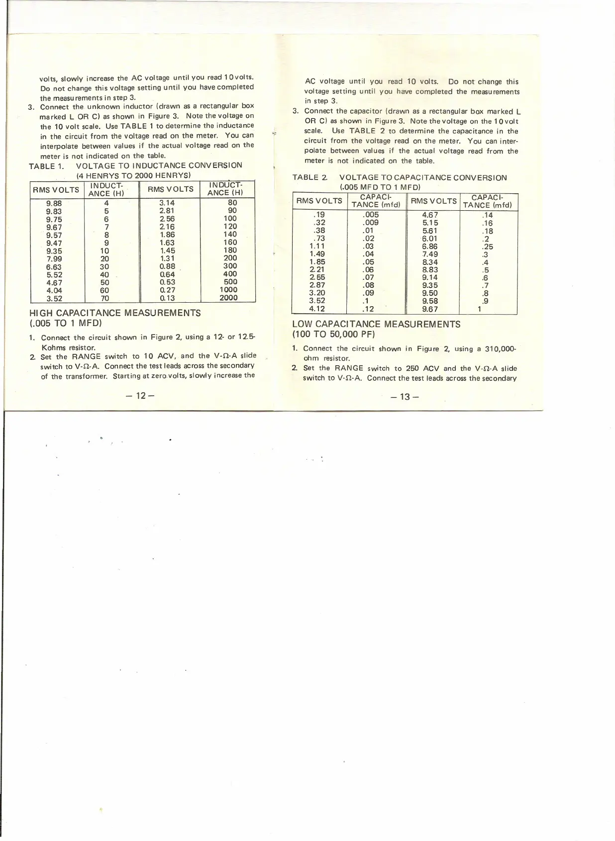
3. Connect the. unknown inductor (drawn as a rectangular box
marked L OR C) asshown in Figure 3. Note the voltage on
the 10 volt scale. UseTABLE 1 to determine the inductance
in the circuit from the voltage read on the meter. You can
interpolate between values if the actual voltage read on the
meter is not indicated on the table.
TABLE 1. VOLTAGE TO INDUCTANCE CONVERSION
(4 HENRYS TO 2000 HENRYS)
INDUCT·
RMSVOLTS
INDUCT·
RMS VOLTS
ANCE (H)
ANCE (H)
9.88
4
3.14 80
9.83
5
2.81 90
9.75
6
256
100
9.67
7
216
120
9.57 8
1.86
140
9.47
9
1.63
160
9.35
10
1.45
180
7.99 20
1.31
200
6.63
30
0.88
300
5.52 40
0.64
400
4.67
50
0.53
500
4.04 60
0.27
1000
3.52
70
0.13
2000
HIGH CAPACITANCE MEASUREMENTS
(.005 TO 1 MFD)
1. Connect the circuit shown in Figure 2, using a 12- or 12.5-
Kohms resistor.
2. Set the RANGE switch to 10 ACV, and the V-n-A slide
switch to v·n-A. Connect the test leadsacrossthe secondary
of the transformer. Starting at zero.volts, slowly increasethe
-12-
-13 -
AC voltage until you read 10 volts. Do not change this
voltage setting until you have completed the measurements
in step 3.
3. Connect the capacitor (drawn as a rectangular box marked L
OR C) as shown in Figure 3. Note the voltage on the 10volt
scale. Use TABLE 2 to determine the capacitance in the
circuit from the voltage read on the meter. You can inter-
polate between values if the actual voltage read from the
meter is not indicated on the table.
TABLE 2. VOLTAGE TO CAPACITANCE CONVERSION
(.005 MFD TO 1 MFD)
RMS VOLTS
CAPAC
1-
RMSVOLTS
CAPACI-
TANCE (mtd)
TANCE (rnfd)
.19 .005
4.67 .14
.32
.009 5.15
.16
.38 .01
5.61
.18
.73
.02
6.01
.2
1.11
.03
6.86 .25
1.49
.04
7.49
.3
1.85
.05
8.34
.4
2.21
.06 8.83
.5
2.55
.07 9.14
.6
2.87
.08
9.35
.7
3.20
.09
9.50
.8
3.52
.1
9.58 .9
4.12
.12
9.67 1
LOW CAPACITANCE MEASUREMENTS
(100 TO 50,000 PF)
1. Connect the circuit shown in Figure 2, using a 310,000-
ohm resistor.
2. Set the RANGE switch to 250 ACV and the V-n-A slide
switch to V-n-A. Connect the test leadsacrossthe secondary
 Loading...