of the transformer. Starting at zero volts, slowly increase
the AC voltage until you read 250 volts. Do not change
the voltage setting until you have completed the measure-
ments in step 3.
3. Connect the capacitor (drawn as a rsctanqular box marked
L OR C) asshown in Figure 3. To avoid an electric shock,
disconnect the variable supply from the power source while
working in the circuit, but do not changethe voltage setting.
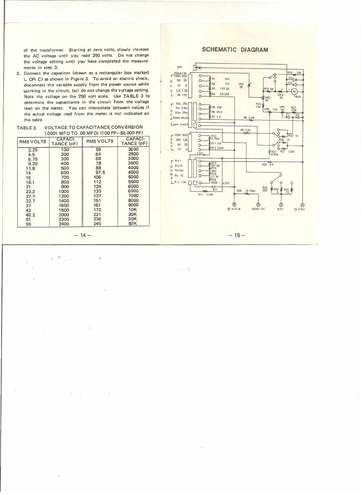
Note the voltage on the 250 volt scale. Use TABLE 3 to
determine the capacitance 'in the circuit from the voltage
read on the meter. You can interpolate between values if
the actual voltage read from the meter is not indicated on
the table.
TABLE 3. VOLTAGE TO CAPACITANCE CONVERSION
(.0001 MFD TO .05 MFD) (100 PF-50,OOOPF)
RMS VOLTS
CAPACI-
RMSVOLTS
CAPACI-
TANCE (pF)
TANCE (pF)
2.25
100
59
2600
4.5
200
64
2800
6.75
300
68
3000
9.25
400
78.
3500
11.8
500
88
4000
14 600
97.5
4500
16
700
106
5000
18.1
800
112
5500
21
900
124
6000
23.3
1000
130
6500
27.7
1200
137
7000
32.7
1400
151
8000
37
1600
161
9000
42
1800
172
10K
46.2
2000
221
20K
51
2200
236
30K
55
2400
245
50K
- 14-
-15-
SCHEMATIC DIAGRAM
OFF
250& 125
r iooo
500
50 25
Al 5M
0
C
10
5
R2 1M
VR2
R3
187.5K
3K
V
2.5 1.25
L
.25.125
R4
56.25K
r
so, ']
A20
5m 2.5m
15K
g
50m 25m
A
soo-
250m
A8 0.48
LSAT. CHEC
A9 CAL.
r
1000 500
A
250 125
C
50
25
V
L
10
5
A13
90-96
A14
950
A15
17.7K
A16
n
o-----J
350K - 430K
~'I~-t--"
A28
L... __
!l__-'9'-'V'--.J A25 18.75M 900
A17 110K
i
I
R23 A27 0.84
665K
A24 9.5
o
eCOM
lQOOV DC