J
Jill MitchellAug 1, 2025
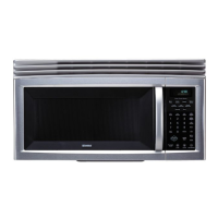
How to troubleshoot absolute humidity sensor issues in a Sears 721.80802400?
- WwalshwilliamAug 1, 2025
A normal absolute humidity sensor should measure approximately 6.0 Kohms between the BK-RD terminals, 3.0 Kohms between the RD-WH terminals, and 3.0 Kohms between the BK-WH terminals. An abnormal sensor will show infinite resistance or approximately 0 ohm.